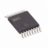
DS2764AE+ Maxim Integrated Products, DS2764AE+ Datasheet - Page 14

DS2764AE+
Manufacturer Part Number
DS2764AE+
Description
IC MON BATT LI-ION HP 16-TSSOP
Manufacturer
Maxim Integrated Products
Datasheet
1.DS2764AETR.pdf
(20 pages)
Specifications of DS2764AE+
Function
Battery Monitor
Battery Type
Lithium-Ion (Li-Ion)
Voltage - Supply
2.5 V ~ 5.5 V
Operating Temperature
-40°C ~ 85°C
Mounting Type
Surface Mount
Package / Case
16-TSSOP
Lead Free Status / RoHS Status
Lead free / RoHS Compliant
Table 2. Memory Map
* Each EEPROM block is read/write until locked by the LOCK command, after which it is read-only.
+ Unique 64 bit ID is a factory option available by special order. Units with IDs do not allow access to block 2 of user EEPROM
PROTECTION REGISTER
The protection register consists of flags that indicate protection circuit status and switches that give conditional
control over the charging and discharging paths. Bits OV, UV, COC, and DOC are set when corresponding
protection conditions occur and remain set until cleared by the host system. The default values of the CE and DE
bits of the protection register are stored in lockable EEPROM in the corresponding bits in address 30h. A recall
data command for EEPROM block 1 recalls the default values into CE and DE. Figure 11 shows the format of the
protection register. The function of each bit is described in detail in the following paragraphs.
Figure 11. Protection Register Format
OV—Overvoltage Flag. When set to 1, this bit indicates the battery pack has experienced an overvoltage condition.
This bit must be reset by the host system.
UV—Undervoltage Flag. When set to 1, this bit indicates the battery pack has experienced an undervoltage
condition. This bit must be reset by the host system.
COC—Charge Overcurrent Flag. When set to 1, this bit indicates the battery pack has experienced a charge-
direction overcurrent condition. This bit must be reset by the host system.
DOC—Discharge Overcurrent Flag. When set to 1, this bit indicates the battery pack has experienced a discharge-
direction overcurrent condition. This bit must be reset by the host system.
ADDRESS (HEX)
F8–FD
09–0B
1A–1F
50–EF
F0–F7
02–06
12–17
20–2F
30–3F
40–47
0C
0D
FE
0E
0F
FF
00
01
07
08
10
11
18
19
BIT 7
OV
EEPROM, block 0
EEPROM, block 1
Protection Register
Status Register
Reserved
EEPROM Register
Special Feature Register
Reserved
Voltage Register MSB
Voltage Register LSB
Current Register MSB
Current Register LSB
Accumulated Current Register MSB
Accumulated Current Register LSB
Reserved
Temperature Register MSB
Temperature Register LSB
Reserved
EEPROM, block 2
Reserved
Unique ID
Reserved
Function Command Register
Reserved
BIT 6
UV
BIT 5
COC
DESCRIPTION
BIT 4
DOC
ADDRESS 00
14 of 20
BIT 3
CC
BIT 2
DC
READ/WRITE
BIT 1
CE
R/W*
R/W*
R/W*
R/W
R/W
R/W
R/W
R/W
R
W
R
R
R
R
R
R
R
+
BIT 0
DE


