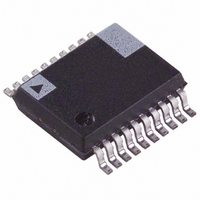
ADE7763ARSZRL Analog Devices Inc, ADE7763ARSZRL Datasheet - Page 26

ADE7763ARSZRL
Manufacturer Part Number
ADE7763ARSZRL
Description
IC ENERGY METERING 1PHASE 20SSOP
Manufacturer
Analog Devices Inc
Datasheet
1.ADE7763ARSZRL.pdf
(56 pages)
Specifications of ADE7763ARSZRL
Input Impedance
390 KOhm
Measurement Error
0.1%
Voltage - I/o High
2.4V
Voltage - I/o Low
0.8V
Current - Supply
3mA
Voltage - Supply
4.75 V ~ 5.25 V
Operating Temperature
-40°C ~ 85°C
Mounting Type
Surface Mount
Package / Case
20-SSOP (0.200", 5.30mm Width)
Meter Type
Single Phase
Ic Function
Single-Phase Active And Apparent Energy Metering IC
Supply Voltage Range
4.75V To 5.25V
Operating Temperature Range
-40°C To +85°C
Digital Ic Case Style
SSOP
No. Of Pins
20
Lead Free Status / RoHS Status
Lead free / RoHS Compliant
For Use With
EVAL-ADE7763ZEB - BOARD EVALUATION FOR ADE7763
Lead Free Status / Rohs Status
Compliant
Other names
ADE7763ARSZRL
ADE7763ARSZRLTR
ADE7763ARSZRLTR
Available stocks
Company
Part Number
Manufacturer
Quantity
Price
Part Number:
ADE7763ARSZRL
Manufacturer:
ADI/亚德诺
Quantity:
20 000
ADE7763
Figure 55 shows the signal processing chain for the active power
calculation. The active power is calculated by low-pass filtering
the instantaneous power signal. Note that when reading the
waveform samples from the output of LPF2, the gain of the
active energy can be adjusted by using the multiplier and watt
gain register (WGAIN[11:0]). The gain is adjusted by writing a
twos complement 12-bit word to the watt gain register.
Equation 11 shows how the gain adjustment is related to the
contents of the watt gain register:
For example, when 0x7FF is written to the watt gain register, the
power output is scaled up by 50%. 0x7FF = 2047d, 2047/2
Similarly, 0x800 = –2048d (signed twos complement) and
power output is scaled by –50%. Each LSB scales the power
output by 0.0244%. Figure 56 shows the maximum code
(hexadecimal) output range for the active power signal (LPF2).
Note that the output range changes depending on the contents
of the watt gain register. The minimum output range is given
when the watt gain register contents are equal to 0x800, and the
maximum range is given by writing 0x7FF to the watt gain
register. This can be used to calibrate the active power (or
energy) calculation.
Output
WGAIN
CURRENT
CHANNEL
VOLTAGE
CHANNEL
=
⎛
⎜ ⎜
⎝
Active
Power
T
×
ACTIVE POWER
⎧
⎨
⎩
LPF2
CLKIN
1
+
SIGNAL
4
TIME (nT)
WGAIN
2
APOS[15:0]
12
+
+
⎫
⎬
⎭
Figure 55. Active Energy Calculation
WAVEFORM
⎞
⎟ ⎟
⎠
REGISTER
VALUES
WGAIN[11:0]
12
= 0.5.
(11)
Rev. B | Page 26 of 56
WDIV[7:0]
%
48
ENERGY CALCULATION
As stated earlier, power is defined as the rate of energy flow.
This relationship is expressed mathematically in Equation 12.
where:
P is power.
E is energy.
Conversely, energy is given as the integral of power.
23
AENERGY[23:0]
P =
E
= Pdt
0xE CCCD
OUTPUTS FROM THE LPF2 ARE
ACCUMULATED (INTEGRATED) IN
THE INTERNAL ACTIVE ENERGY REGISTER
∫
0xF 999A
dE
0xCCCD
0x1 3333
0x0 0000
0xF 3333
dt
0x6666
Figure 56. Active Power Calculation Output Range
0
0x000
UPPER 24 BITS ARE
ACCESSIBLE THROUGH
AENERGY[23:0] REGISTER
CALIBRATION RANGE
ACTIVE POWER
{WGAIN[11:0]}
0x7FF
0
0x800
POSITIVE
POWER
NEGATIVE
POWER
(12)
(13)


