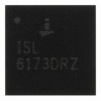
ISL6173DRZA Intersil, ISL6173DRZA Datasheet

ISL6173DRZA
Specifications of ISL6173DRZA
Available stocks
Related parts for ISL6173DRZA
ISL6173DRZA Summary of contents
Page 1
... RANGE (Note) MARKING (°C) ISL6173DRZA ISL6173DRZ 5x5 QFN L28.5x5 ISL6173DRZA-T ISL6173DRZ 5x5 QFN Tape & Reel ISL6173EVAL3 Evaluation Platform NOTE: Intersil Pb-free plus anneal products employ special Pb-free material sets; molding compounds/die attach materials and 100% matte tin plate termination finish, which are RoHS compliant and compatible with both SnPb and Pb-free soldering operations ...
Page 2
Block Diagram Vin Iset Rset 1.178V Iref OCREF Current Mirror Rref BIAS 10K EN1 BIAS 10K RTR/LTCH BIAS CPQ+ Cp CPQ- CPVDD Cv FIGURE 2. ISL6173 - INTERNAL BLOCK-DIAGRAM OF THE IC - CHANNEL ONE ONLY 2 ISL6173 Io Rsns ...
Page 3
Pinout Pin Descriptions PIN NAME FUNCTION 1 SNS1 Current Sense Input 2 VO1 Output Voltage 1 3 SS1 Soft-Start Duration Set Input 4 GT1 Gate Drive Output 5 FLT1 Fault Output 6 PG1 Power Good Output 7 CT1 Timer Capacitor ...
Page 4
Pin Descriptions (Continued) PIN NAME FUNCTION 11 CPQ- Charge Pump Capacitor Low Side 12 BIAS Chip Bias Voltage 13 CPQ+ Charge Pump Capacitor High Side 14 CPVDD Charge Pump Output 15 CT2 Timer Capacitor 16 PG2 Power Good Output 17 ...
Page 5
Absolute Maximum Ratings VBIAS . . . . . . . . . . . . . . . . . . . . . . . . . . . . . . . . . . . . ...
Page 6
Electrical Specifications V = 2.5V to +3.3V PARAMETER GATE Voltage BIAS Supply Current POR Rising Threshold POR Falling Threshold POR Threshold Hysteresis I/O Undervoltage Comparator Falling Threshold Undervoltage Comparator Hysteresis EN Rising Threshold EN Falling Threshold EN Hysteresis ...
Page 7
Typical Performance Curves 22nF 1.0 1.4 1.7 2.0 2.3 V_BIAS(V) FIGURE 3. I_BIAS vs V_BIAS ...
Page 8
Typical Performance Curves 10000 1000 100 0.1 0. (nF) G FIGURE 9. WOC RESPONSE vs LOAD CAPACITANCE 8 ISL6173 (at 25°C unless otherwise specified) (Continued) 3 2.5 2 1 8.7 ...
Page 9
Detailed Description of Operation ISL6173 targets dual voltage hot-swap applications with a bias of 2.1V to 3.6VDC and the voltages being controlled down to 0.7VDC. The IC’s main function is to limit and regulate the inrush current into the loads. ...
Page 10
MOSFET after a wait period, during which C is charged and discharged 64 times T and the retry attempt takes place on the 65th time. This wait period allows the MOSFET junction to cool ...
Page 11
The two channels can be forced to track each other by simply tying their SS pins together and using a common SS capacitor. In addition, their EN pins also must be tied together. Typical Start-up waveforms in this mode are ...
Page 12
IC Operation State Diagram Gate Pulldow n Io>>I CR (WOC) Output Io>I Voltage Available Vuv<633mV Vuv>645mV PG Asserted 12 ISL6173 No Pow er Apply Pow er Bias>1V PG & FLT Outputs Valid Bias>2V EN De-asserted FLT Cleared EN Asserted Io>I ...
Page 13
Applications Information Selection of External Components The typical application circuit of Figure 2 has been used for this section, which provides guidelines to select the external component values. MOSFET (Q1) This component should be selected on the basis of its ...
Page 14
Soft-Start Capacitor Selection (C The rate of change of voltage (dv/dt) on this capacitor, which is determined by the internal 10µA current source, is the same as that on the output load capacitance. Hence, the value of this capacitor directly ...
Page 15
FIGURE 18. WOC OPERATION Channel 1 is Vgate, Channel 2 is the pulse generator output and Channel 3 is Vout. Note how Vgate gets immediately pulled down to zero volts up on load application mode, however, Vgate always ...
Page 16
... MFG P/N MANUFACTURER Nichicon Nichicon Any Any Any Any Any Any Any Any Any ON Semi Stanley Stanley Any Any International Rectifier Any Any Any Any Any Any Any Any Any Any Any Any Any Any Intersil Intersil C & K FN9186.3 January 3, 2006 ...
Page 17
Schematic, ISL6173 Eval1 J4 Vi_1 3.3V Vi_1 C1 220µF J1 CON2 C4 0.1µ 0.1µF J5 TP11 SW1 SW2 TP12 SW3 OPEN = Disable CLOSE = Enable OPEN = Latch GND_IN CLOSE = Retry J6 CON2 C18 J3 ...
Page 18
Schematic, ISL6173 Eval1 (Continued) VO1 TP31 4 2 J11 R59 49.9 VO2 TP32 4 2 J12 R60 49 TP28 1 R38 R37 R42 TP30 IRF7821 8 SW4 R33 ...
Page 19
ISL6173 Eval 1 - Component Layout FIGURE 22. ...
Page 20
... Accordingly, the reader is cautioned to verify that data sheets are current before placing orders. Information furnished by Intersil is believed to be accurate and reliable. However, no responsibility is assumed by Intersil or its subsidiaries for its use; nor for any infringements of patents or other rights of third parties which may result from its use ...


