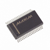
MAX5952AEAX+ Maxim Integrated Products, MAX5952AEAX+ Datasheet - Page 6

MAX5952AEAX+
Manufacturer Part Number
MAX5952AEAX+
Description
IC PSE CNTRLR FOR POE 36-SSOP
Manufacturer
Maxim Integrated Products
Type
Power Over Ethernet Controller (PoE)r
Datasheet
1.MAX5952AUAX.pdf
(50 pages)
Specifications of MAX5952AEAX+
Applications
Remote Peripherals (Industrial Controls, Cameras, Data Access)
Internal Switch(s)
No
Operating Temperature
-40°C ~ 85°C
Mounting Type
Surface Mount
Package / Case
36-BSOP (0.300", 7.5mm Width)
Product
Controllers & Switches
Supply Voltage (max)
5.5 V
Supply Voltage (min)
1.71 V
Power Dissipation
941 mW
Operating Temperature Range
- 40 C to + 85 C
Mounting Style
SMD/SMT
Supply Current
4.8 mA
Input Voltage
60V
Digital Ic Case Style
SSOP
No. Of Pins
36
Uvlo
28.5V
Frequency
400kHz
Interface
I2C
Termination Type
SMD
Rohs Compliant
Yes
Filter Terminals
SMD
Controller Type
Power Over Ethernet PD
Lead Free Status / RoHS Status
Lead free / RoHS Compliant
ELECTRICAL CHARACTERISTICS (continued)
(V
V
wise.) (Note 2)
High-Power, Quad, PSE Controller
for Power-Over-Ethernet
6
DIGITAL INPUTS/OUTPUTS (Referred to DGND)
Digital Input Low
Digital Input High
Internal Input Pullup/Pulldown
Resistor
O p en- D r ai n O utp ut Low V ol tag e
Digital Input Leakage
Open-Drain Leakage
TIMING
Startup Time
Fault Time
Port Turn-Off Time
Detection Reset Time
Detection Time
M i d sp an M od e D etecti on D el ay
Classification Time
V
Restart Timer
Watchdog Clock Period
ADC PERFORMANCE
Resolution
Range
LSB Step Size
Integral Nonlinearity (Relative)
AGND
AGND
EEUVLO
_______________________________________________________________________________________
= +48V, V
= 32V to 60V, V
PARAMETER
Turn-On Delay
DGND
EE
= +48V, V
= 0V, V
DD
DD
SYMBOL
t
RESTART
to V
t
t
t
t
CLASS
START
FAULT
R
= (V
t
t
DMID
t
V
t
V
I
INL
V
I
OFF
DET
DLY
WD
DL
OL
DIN
OL
IH
IL
DGND
DGND
= +3.3V, all voltages are referenced to V
Pullup (pulldown) resistor to V
set default level
I
Input connected to the pull voltage
Open-drain high impedance, V
Time during which a current limit set by
V
turned on (Note 5)
Maximum allowed time for an overcurrent
condition set by V
Minimum delay between any port turning off,
does not apply in case of a reset
Time allowed for the port voltage to reset
before detection starts
Maximum time allowed before detection is
completed
Time allowed for classification
Time V
thresholds before the device operates
Time a port has to wait
before turning on after an
overcurrent fault,
RSTR_EN_ bits = high
Rate of decrement of the watchdog timer
SINK
+ 3.3V), T
SU_LIM
= 15mA
AGND
is allowed, starts when the GATE_ is
A
= +25°C. Currents are positive when entering the pin and negative other-
must be above the V
CONDITIONS
FLT_LIM
after startup (Note 5)
RSTR bits = 00
RSTR bits = 01
RSTR bits = 10
RSTR bits = 11
DD
O
= 3.3V
(DGND) to
EEUVLO
EE
, unless otherwise noted. Typical values are at
MIN
2.4
2.0
25
50
50
2
t
t
t
FAULT
FAULT
FAULT
TYP
16 x
32 x
64 x
0.51
164
0.5
0.5
50
60
60
80
19
0
9
1
MAX
330
0.9
0.4
2.4
75
70
70
90
23
2
2
4
UNITS
LSB
Bits
mV
ms
ms
ms
ms
ms
ms
ms
ms
ms
kΩ
µA
µA
V
V
V
V
s


