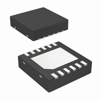
LM2759SD/NOPB National Semiconductor, LM2759SD/NOPB Datasheet - Page 11

LM2759SD/NOPB
Manufacturer Part Number
LM2759SD/NOPB
Description
IC LED DRIVER PHOTO FLASH 12-LLP
Manufacturer
National Semiconductor
Series
PowerWise®r
Type
Photo Flash LED (I²C Interface)r
Datasheet
1.LM2759SDNOPB.pdf
(14 pages)
Specifications of LM2759SD/NOPB
Constant Current
Yes
Topology
Switched Capacitor (Charge Pump)
Number Of Outputs
1
Internal Driver
Yes
Type - Primary
Flash/Torch
Frequency
700kHz ~ 1.3MHz
Voltage - Supply
*
Voltage - Output
2 V ~ 4 V
Mounting Type
Surface Mount
Package / Case
12-LLP
Operating Temperature
-30°C ~ 85°C
Current - Output / Channel
1A
Internal Switch(s)
Yes
Efficiency
90%
Led Driver Application
Camera Flash In Mobile Phones, Flash For Digital Cameras
No. Of Outputs
1
Output Current
1A
Output Voltage
5.1V
Input Voltage
2.7V To 5.5V
Rohs Compliant
Yes
Lead Free Status / RoHS Status
Lead free / RoHS Compliant
Other names
LM2759SDTR
Available stocks
Company
Part Number
Manufacturer
Quantity
Price
Company:
Part Number:
LM2759SD/NOPB
Manufacturer:
National Semiconductor
Quantity:
1 790
SETTING LED CURRENT
The current through the LED is set by programming the ap-
propriate register with the desired current level code for Flash
and Torch. The time that Flash mode is active is dependent
on the lesser of the duration that it is set to "ON" (via I
the Strobe pin), or the duration of the Flash Timeout. Use the
tables below to select the desired current level.
Using the part in conditions where the junction temperature
might rise above the rated maximum requires that the oper-
ating ranges and/or conditions be de-rated. The printed circuit
board also must be carefully laid out to account for high ther-
mal dissipation in the part.
CODE (Hex)
CODE (Hex)
0A
0B
0C
0D
0E
0F
0A
0B
0C
0D
0E
0F
00
01
02
03
04
05
06
07
08
09
Torch Current Table (Reg xA0)
00
01
02
03
04
05
06
07
08
09
Flash Current Table (Reg xB0)
TORCH CURRENT (mA)
FLASH CURRENT (mA)
1010
150
220
280
350
410
470
530
590
650
710
770
830
890
950
100
110
120
130
140
150
160
170
180
80
15
30
40
50
65
80
90
2
C or
11
FLASH TIME-OUT FEATURE
Time-out Protection Circuitry disables the current sink when
either the Strobe pin is held at logic high or the Flash mode is
enabled via the I
grammed timeout duration. This prevents the device from
self-heating due to the high power dissipation during Flash
conditions. During the time-out condition, voltage will still be
present on V
in no current through the Flash LED. When the device goes
into a time-out condition, disabling and then re-enabling the
device will reset the time-out. Use the table below to set the
desired Flash timeout duration.
CAPACITOR SELECTION
The LM2759 requires 4 external capacitors for proper opera-
tion. Surface-mount multi-layer ceramic capacitors are rec-
ommended. These capacitors are small, inexpensive and
have very low equivalent series resistance (ESR <20 mΩ
typ.). Tantalum capacitors, OS-CON capacitors, and alu-
minum electrolytic capacitors are not recommended for use
with the LM2759 due to their high ESR, as compared to ce-
ramic capacitors. For most applications, ceramic capacitors
with X7R or X5R temperature characteristic are preferred for
use with the LM2759. These capacitors have tight capaci-
tance tolerance (as good as ±10%) and hold their value over
temperature (X7R: ±15% over -55°C to 125°C; X5R: ±15%
over -55°C to 85°C). Capacitors with Y5V or Z5U temperature
characteristic are generally not recommended for use with the
LM2759. Capacitors with these temperature characteristics
typically have wide capacitance tolerance (+80%, -20%) and
vary significantly over temperature (Y5V: +22%, -82% over
-30°C to +85°C range; Z5U: +22%, -56% over +10°C to +85°
C range). Under some conditions, a nominal 1 μF Y5V or Z5U
capacitor could have a capacitance of only 0.1 μF. Such detri-
mental deviation is likely to cause Y5V and Z5U capacitors to
fail to meet the minimum capacitance requirements of the
LM2759. The voltage rating of the output capacitor should be
6.3V or more. For example, a 6.3V 0603 4.7 μF output ca-
pacitor (TDK C1608X5R0J475) is acceptable for use with the
LM2759, as long as the capacitance on the output does not
fall below a minimum of 3μF in the intended application. All
other capacitors should have a voltage rating at or above the
maximum input voltage of the application and should have a
minimum capacitance of 1 μF.
CODE (Hex)
Flash Timeout Duration (Reg xC0)
OUT
00
01
02
03
04
05
06
07
2
but the current sink will be shut off, resulting
C compatible interface longer than the pro-
TIME (ms)
1100
125
250
375
500
625
750
60
www.national.com


