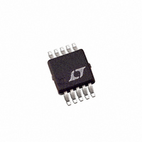
LT3003EMSE#PBF Linear Technology, LT3003EMSE#PBF Datasheet - Page 4

LT3003EMSE#PBF
Manufacturer Part Number
LT3003EMSE#PBF
Description
IC LED DRIVER BALLASTER 10-MSOP
Manufacturer
Linear Technology
Type
LED Ballasterr
Datasheet
1.LT3003EMSEPBF.pdf
(16 pages)
Specifications of LT3003EMSE#PBF
Topology
PWM, Step-Down (Buck), Step-Up (Boost)
Number Of Outputs
3
Internal Driver
Yes
Type - Primary
Automotive, Backlight
Voltage - Supply
3 V ~ 40 V
Mounting Type
Surface Mount
Package / Case
10-MSOP Exposed Pad, 10-HMSOP, 10-eMSOP
Operating Temperature
-40°C ~ 125°C
Current - Output / Channel
350mA
Internal Switch(s)
Yes
Lead Free Status / RoHS Status
Lead free / RoHS Compliant
Voltage - Output
-
Frequency
-
Efficiency
-
Available stocks
Company
Part Number
Manufacturer
Quantity
Price
PIN FUNCTIONS
LT3003
TYPICAL PERFORMANCE CHARACTERISTICS
LED1 (Pin 1): Controlled current input for a string of LEDs
with a cathode lead connected to the pin. Connect the fi rst
string of LEDs to this pin.
LED2 (Pin 2): Controlled current input for a string of LEDs
with a cathode lead connected to the pin. Connect the sec-
ond string of LEDs to this pin.
LED3 (Pin 3): Controlled current input for a string of LEDs
with a cathode lead connected to the pin. Connect the third
string of LEDs to this pin.
V
V
locally bypassed with a capacitor to ground. V
the internal control circuitry.
PWM (Pin 6): Input Pin for PWM Dimming Control. A
PWM signal above 0.5V (on threshold) turns the LT3003
4
MAX
IN
• Boost: Connect to V
• Buck Mode: Connect to Input Supply
• Buck-Boost Mode: Connect to V
• Boost: Connect to Input Supply
• Buck Mode: Connect to Input Supply
• Buck-Boost Mode: Connect to V
(Pin 5): Input Supply, Upper Rail. This pin must be
(Pin 4):
35
30
25
20
15
10
5
0
50
V
IN
Quiescent Current vs I
100
OUT
150
I
LED
200
(mA)
OUT
OUT
250
LED
300
3003 G07
IN
350
powers
channels on. A PWM signal below 0.5V completely discon-
nects each LED string. If the application does not require
PWM dimming, then the PWM pin can be left either open
(an internal 10µA source current pulls PWM high) or it
can be connected to a supply between 0.5V to 15V.
OT1 (Pin 7): Overtemperature Output. OT1 pulls 100µA
from the pin when the junction temperature exceeds
125°C. The part has to cool down by 6°C for the fl ag to
reset; ideal for providing an overtemperature fl ag to the
system microprocessor.
OT2 (Pin 8): Overtemperature Output. OT2 Pulls 300µA
from the pin when the junction temperature exceeds
125°C. The part has to cool down by 6°C for the fl ag to
reset; ideal for connecting to the switching regulator g
error amplifi er output to defeat switching.
SHDN (Pin 9): Micropower Shutdown Pin. Below 0.7V
shuts down the IC. Typically I
• Boost: Connect to System Shutdown Signal or V
• Buck Mode: Connect to System Shutdown Signal
• Buck-Boost Mode: If PWM dimming, connect to PWM
or V
(Pin 6); if no PWM dimming, connect to system shut-
down signal or V
16
14
12
10
8
6
4
2
0
V
3
IN
SHDN = 0
IN
T
Shutdown Current vs V
8
A
= 25°C unless otherwise noted.
13
18
V
IN
IN
23
(V)
28
VIN
IN
33
= 4µA for SHDN = 0V.
3003 G08
38
3003fa
IN
m


