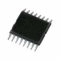
PCA9922PW,112 NXP Semiconductors, PCA9922PW,112 Datasheet - Page 23

PCA9922PW,112
Manufacturer Part Number
PCA9922PW,112
Description
IC LED DRIVER 8-CH 16-TSSOP
Manufacturer
NXP Semiconductors
Type
Linear (Serial Interface)r
Datasheet
1.PCA9922PW112.pdf
(27 pages)
Specifications of PCA9922PW,112
Constant Current
Yes
Number Of Outputs
8
Internal Driver
Yes
Type - Primary
General Purpose
Type - Secondary
Color
Frequency
25MHz
Voltage - Supply
3.3 V ~ 5.5 V
Voltage - Output
5.5V
Mounting Type
Surface Mount
Package / Case
16-TSSOP
Operating Temperature
-40°C ~ 85°C
Current - Output / Channel
60mA
Internal Switch(s)
Yes
Lead Free Status / RoHS Status
Lead free / RoHS Compliant
Efficiency
-
Topology
-
Lead Free Status / Rohs Status
Details
Other names
935285711112
NXP Semiconductors
17. Soldering of through-hole mount packages
PCA9922
Product data sheet
17.1 Introduction to soldering through-hole mount packages
17.2 Soldering by dipping or by solder wave
17.3 Manual soldering
For further information on temperature profiles, refer to Application Note AN10365
“Surface mount reflow soldering description”.
This text gives a very brief insight into wave, dip and manual soldering.
Wave soldering is the preferred method for mounting of through-hole mount IC packages
on a printed-circuit board.
Driven by legislation and environmental forces the worldwide use of lead-free solder
pastes is increasing. Typical dwell time of the leads in the wave ranges from
3 seconds to 4 seconds at 250 °C or 265 °C, depending on solder material applied, SnPb
or Pb-free respectively.
The total contact time of successive solder waves must not exceed 5 seconds.
The device may be mounted up to the seating plane, but the temperature of the plastic
body must not exceed the specified maximum storage temperature (T
printed-circuit board has been pre-heated, forced cooling may be necessary immediately
after soldering to keep the temperature within the permissible limit.
Apply the soldering iron (24 V or less) to the lead(s) of the package, either below the
seating plane or not more than 2 mm above it. If the temperature of the soldering iron bit is
less than 300 °C it may remain in contact for up to 10 seconds. If the bit temperature is
between 300 °C and 400 °C, contact may be up to 5 seconds.
Fig 18. Temperature profiles for large and small components
temperature
MSL: Moisture Sensitivity Level
All information provided in this document is subject to legal disclaimers.
8-channel constant current LED driver with output error detection
Rev. 2 — 6 April 2011
= minimum soldering temperature
maximum peak temperature
minimum peak temperature
= MSL limit, damage level
temperature
peak
stg(max)
PCA9922
© NXP B.V. 2011. All rights reserved.
001aac844
). If the
time
23 of 27


