LP5521TMX/NOPB National Semiconductor, LP5521TMX/NOPB Datasheet - Page 15
LP5521TMX/NOPB
Manufacturer Part Number
LP5521TMX/NOPB
Description
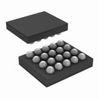
IC LED DRIVER RGB 25-USMD
Manufacturer
National Semiconductor
Series
PowerWise®r
Type
RGB LED Driverr
Datasheet
1.LP5521TMNOPB.pdf
(40 pages)
Specifications of LP5521TMX/NOPB
Constant Current
Yes
Topology
PWM, Switched Capacitor (Charge Pump)
Number Of Outputs
3
Internal Driver
Yes
Type - Primary
Backlight, Light Management Unit (LMU)
Type - Secondary
RGB
Frequency
1.25MHz
Voltage - Supply
2.7 V ~ 5.5 V
Voltage - Output
4.55V
Mounting Type
Surface Mount
Package / Case
20-MicroSMD
Operating Temperature
-30°C ~ 85°C
Current - Output / Channel
25.5mA
Internal Switch(s)
Yes
Efficiency
95%
Lead Free Status / RoHS Status
Lead free / RoHS Compliant
Other names
LP5521TMX
Available stocks
Company
Part Number
Manufacturer
Quantity
Price
Company:

Part Number:
LP5521TMX/NOPB
Manufacturer:
TI
Quantity:
57 001
Part Number:
LP5521TMX/NOPB
Manufacturer:
TI/德州仪器
Quantity:
20 000


LED Driver Operational Description
The LP5521 LED drivers are constant current sources with 8-
bit PWM control. Output current can be programmed with I
register up to 25.5 mA. Current setting resolution is 100 μA
(8-bit control).
R driver has two modes: current source can be connected to
battery (V
connected to battery, automatic charge pump gain control is
not used for this output. This approach provides better effi-
ciency when LED with low V
battery voltage is high enough to drive this LED in all condi-
tions. R driver mode can be selected with I
When address 08H, bit R_TO_BATT = 1, R current source is
connected to battery. When it is 0 (default), R current source
is connected to charge pump same way as in G and B drivers.
G and B drivers are always connected to charge pump output.
Some LED configuration examples are given in table below.
When LEDs with low V
erating in bypass mode (1x). This eliminates the need of
having double drivers for all outputs; one connected to battery
and another connected to charge pump output. When LP5521
is driving a RGB LED, R channel can be configured to use
battery power. This configuration increases power efficiency
by minimizing the voltage drop across the LED driver.
DD
) or to charge pump output. If current source is
CURRENT
R_CURRENT register (05H), G_CURRENT register (06H), B_CURRENT register (07H):
PWM_HF
LOG_EN
Name
Name
Name
F
are used, charge pump can be op-
F
is connected to R driver, and
7:0
Bit
Bit
Bit
7
6
2
C register bit.
Description
Logarithmic PWM adjustment enable bit
0 = Linear adjustment
1 = Logarithmic adjustment
Description
PWM clock frequency
0 = 256 Hz, frequency defined by 32 kHz clock (internal or
external)
1 = 558 Hz, frequency defined by internal oscillator
0000 0000
0000 0001
0000 0010
0000 0011
0000 0100
0000 0101
0000 0110
1010 1111
1111 1011
1111 1100
1111 1101
1111 1110
1111 1111
ENABLE register (00H):
CONFIG register (08H):
bin
...
...
2
C
15
PWM frequency is either 256 Hz or 558 Hz, frequency is set
with PWM_HF bit in register 08H. When PWM_HF is 0, then
the frequency is 256 Hz, and when bit is 1 then the PWM
frequency is 558 Hz. Brightness adjustment is either linear or
logarithmic. This can be set with register 00H LOG_EN bit.
When LOG_EN = 0 linear adjustment scale is used, and when
LOG_EN = 1 logarithmic scale is used. By using logarithmic
scale the visual effect seems linear to the eye. Register con-
trol bits are presented in following tables:
3 x low V
1 x low V
Configuration
RGB LED with
3 x white LED
hex
AF
FB
FC
FD
FE
00
01
02
03
04
05
06
FF
...
...
low V
(R output)
Current setting
Description
F
F
F
red
LED
LED
LED configuration examples
dec
175
251
252
253
254
255
R output
...
...
to BATT
0
1
2
3
4
5
6
X
X
R output
17.5 (def)
to CP
25.1
25.2
25.3
25.4
25.5
mA
0.0
0.1
0.2
0.3
0.4
0.5
0.6
X
X
...
...
Auto (1x or 1.5x)
Auto (1x or 1.5x)
CP Mode
Disabled
www.national.com
1x
Related parts for LP5521TMX/NOPB
Image
Part Number
Description
Manufacturer
Datasheet
Request
R

Part Number:
Description:
Manufacturer:
National Semiconductor
Datasheet:

Part Number:
Description:
IC LED DRIVER RGB 25-USMD
Manufacturer:
National Semiconductor
Datasheet:

Part Number:
Description:
Programmable Three Channel LED Driver
Manufacturer:
NSC [National Semiconductor]
Datasheet:
Part Number:
Description:
National Semiconductor [8-Bit D/A Converter]
Manufacturer:
National Semiconductor
Datasheet:
Part Number:
Description:
National Semiconductor [Media Coprocessor]
Manufacturer:
National Semiconductor
Datasheet:
Part Number:
Description:
Digitally Controlled Tone and Volume Circuit with Stereo Audio Power Amplifier, Microphone Preamp Stage and National 3D Sound
Manufacturer:
National Semiconductor
Datasheet:
Part Number:
Description:
Digitally Controlled Tone and Volume Circuit with Stereo Audio Power Amplifier, Microphone Preamp Stage and National 3D Sound
Manufacturer:
National Semiconductor
Datasheet:
Part Number:
Description:
AC97 Rev 2 Codec with Sample Rate Conversion and National 3D Sound
Manufacturer:
National Semiconductor
Part Number:
Description:
Manufacturer:
National Semiconductor
Datasheet:
Part Number:
Description:
Manufacturer:
National Semiconductor
Datasheet:
Part Number:
Description:
General Purpose, Low Voltage, Low Power, Rail-to-Rail Output Operational Amplifiers
Manufacturer:
National Semiconductor
Datasheet:
Part Number:
Description:
8-bit 20 MSPS flash A/D converter.
Manufacturer:
National Semiconductor
Datasheet:
Part Number:
Description:
Low Noise Quad Operational Amplifier
Manufacturer:
National Semiconductor
Datasheet:
Part Number:
Description:
Quad Differential Line Receivers
Manufacturer:
National Semiconductor
Datasheet: