LP5521TMX/NOPB National Semiconductor, LP5521TMX/NOPB Datasheet - Page 27
LP5521TMX/NOPB
Manufacturer Part Number
LP5521TMX/NOPB
Description
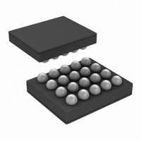
IC LED DRIVER RGB 25-USMD
Manufacturer
National Semiconductor
Series
PowerWise®r
Type
RGB LED Driverr
Datasheet
1.LP5521TMNOPB.pdf
(40 pages)
Specifications of LP5521TMX/NOPB
Constant Current
Yes
Topology
PWM, Switched Capacitor (Charge Pump)
Number Of Outputs
3
Internal Driver
Yes
Type - Primary
Backlight, Light Management Unit (LMU)
Type - Secondary
RGB
Frequency
1.25MHz
Voltage - Supply
2.7 V ~ 5.5 V
Voltage - Output
4.55V
Mounting Type
Surface Mount
Package / Case
20-MicroSMD
Operating Temperature
-30°C ~ 85°C
Current - Output / Channel
25.5mA
Internal Switch(s)
Yes
Efficiency
95%
Lead Free Status / RoHS Status
Lead free / RoHS Compliant
Other names
LP5521TMX
Available stocks
Company
Part Number
Manufacturer
Quantity
Price
Company:

Part Number:
LP5521TMX/NOPB
Manufacturer:
TI
Quantity:
57 001
Part Number:
LP5521TMX/NOPB
Manufacturer:
TI/德州仪器
Quantity:
20 000


1 μF for C
470 nF for C
LEDs
Recommended External Components
CAPACITOR SELECTION
The LP5521 requires 4 external capacitors for proper opera-
tion (C
mount multi-layer ceramic capacitors are recommended.
These capacitors are small, inexpensive and have very low
equivalent series resistance (ESR < 20 mΩ typ.). Tantalum
capacitors, OS-CON capacitors, and aluminum electrolytic
capacitors are not recommended for use with the LP5521 due
to their high ESR, as compared to ceramic capacitors.
For most applications, ceramic capacitors with X7R or X5R
temperature characteristic are preferred for use with the
LP5521. These capacitors have tight capacitance tolerance
(as good as ±10%) and hold their value over temperature
(X7R: ±15% over -55°C to 125°C; X5R: ±15% over -55°C to
85°C).
Capacitors with Y5V or Z5U temperature characteristic are
generally not recommended for use with the LP5521. Capac-
itors with these temperature characteristics typically have
List of Recommended External Components
C1005X5R1A105K
C1005X5R1A474K
ECJUVBPA105M
ECJ0EB1A105M
ECJ0EB0J474K
IN
Model
OUT
= C
FLY1-2
and C
OUT
= 1 μF, C
IN
Ceramic X5R, array of two
FLY1
= C
Ceramic X5R
Ceramic X5R
Ceramic X5R
Ceramic X5R
FLY2
Type
= 470 nF). Surface-
Panasonic
Panasonic
Panasonic
Vendor
27
TDK
TDK
wide capacitance tolerance (+80%, -20%) and vary signifi-
cantly over temperature (Y5V: +22%, -82% over -30°C to
+85°C range; Z5U: +22%, -56% over +10°C to +85°C range).
Under some conditions, a nominal 1 μF Y5V or Z5U capacitor
could have a capacitance of only 0.1 μF. Such detrimental
deviation is likely to cause Y5V and Z5U capacitors to fail to
meet the minimum capacitance requirements of the LP5521.
The minimum voltage rating acceptable for all capacitors is
6.3V. The recommended voltage rating of the output capaci-
tor is 10V to account for DC bias capacitance losses.
Some ceramic capacitors, especially those in small pack-
ages, exhibit a strong capacitance reduction with the
increased applied voltage (DC bias effect). The capaci-
tance value can fall below half of the nominal capaci-
tance. Choose output and input capacitor with DC bias
voltage effect better than –50% at 5V voltage (0.5 μF at
5V).
User Defined
Voltage Rating
10 V
10 V
10 V
10 V
10 V
Size inch (mm)
0402 (1005)
0402 (1005)
0402 (1005)
0402 (1005)
0504
www.national.com
Related parts for LP5521TMX/NOPB
Image
Part Number
Description
Manufacturer
Datasheet
Request
R

Part Number:
Description:
Manufacturer:
National Semiconductor
Datasheet:

Part Number:
Description:
IC LED DRIVER RGB 25-USMD
Manufacturer:
National Semiconductor
Datasheet:

Part Number:
Description:
Programmable Three Channel LED Driver
Manufacturer:
NSC [National Semiconductor]
Datasheet:
Part Number:
Description:
National Semiconductor [8-Bit D/A Converter]
Manufacturer:
National Semiconductor
Datasheet:
Part Number:
Description:
National Semiconductor [Media Coprocessor]
Manufacturer:
National Semiconductor
Datasheet:
Part Number:
Description:
Digitally Controlled Tone and Volume Circuit with Stereo Audio Power Amplifier, Microphone Preamp Stage and National 3D Sound
Manufacturer:
National Semiconductor
Datasheet:
Part Number:
Description:
Digitally Controlled Tone and Volume Circuit with Stereo Audio Power Amplifier, Microphone Preamp Stage and National 3D Sound
Manufacturer:
National Semiconductor
Datasheet:
Part Number:
Description:
AC97 Rev 2 Codec with Sample Rate Conversion and National 3D Sound
Manufacturer:
National Semiconductor
Part Number:
Description:
Manufacturer:
National Semiconductor
Datasheet:
Part Number:
Description:
Manufacturer:
National Semiconductor
Datasheet:
Part Number:
Description:
General Purpose, Low Voltage, Low Power, Rail-to-Rail Output Operational Amplifiers
Manufacturer:
National Semiconductor
Datasheet:
Part Number:
Description:
8-bit 20 MSPS flash A/D converter.
Manufacturer:
National Semiconductor
Datasheet:
Part Number:
Description:
Low Noise Quad Operational Amplifier
Manufacturer:
National Semiconductor
Datasheet:
Part Number:
Description:
Quad Differential Line Receivers
Manufacturer:
National Semiconductor
Datasheet: