LP5521TMX/NOPB National Semiconductor, LP5521TMX/NOPB Datasheet - Page 17
LP5521TMX/NOPB
Manufacturer Part Number
LP5521TMX/NOPB
Description
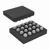
IC LED DRIVER RGB 25-USMD
Manufacturer
National Semiconductor
Series
PowerWise®r
Type
RGB LED Driverr
Datasheet
1.LP5521TMNOPB.pdf
(40 pages)
Specifications of LP5521TMX/NOPB
Constant Current
Yes
Topology
PWM, Switched Capacitor (Charge Pump)
Number Of Outputs
3
Internal Driver
Yes
Type - Primary
Backlight, Light Management Unit (LMU)
Type - Secondary
RGB
Frequency
1.25MHz
Voltage - Supply
2.7 V ~ 5.5 V
Voltage - Output
4.55V
Mounting Type
Surface Mount
Package / Case
20-MicroSMD
Operating Temperature
-30°C ~ 85°C
Current - Output / Channel
25.5mA
Internal Switch(s)
Yes
Efficiency
95%
Lead Free Status / RoHS Status
Lead free / RoHS Compliant
Other names
LP5521TMX
Available stocks
Company
Part Number
Manufacturer
Quantity
Price
Company:

Part Number:
LP5521TMX/NOPB
Manufacturer:
TI
Quantity:
57 001
Part Number:
LP5521TMX/NOPB
Manufacturer:
TI/德州仪器
Quantity:
20 000


DISABLED
Each channel can be configured to disabled mode. LED out-
put current will be 0 during this mode. Disabled mode resets
respective channel’s PC.
LOAD Program
LP5521 can store 16 commands for each channel (R, G, B).
Each command consists of 16 bits. Because one register has
only 8 bits, one command requires two I
es. In order to reduce program load time LP5521 supports
address auto incrementation. Register address is increment-
ed after each 8 data bits. Whole program memory can be
written in one I
Program memory is defined in the LP5521 register table, 10H
to 2FH for R channel, 30H to 4FH for G channel and 50H to
6FH for B channel. In order to be able to access program
memory at least one channel operation mode needs to be
LOAD Program.
Memory writes are allowed only to the channel in LOAD
mode. All channels are in hold while one or several channels
are in LOAD program mode, and PWM values are frozen for
the channels which are not in LOAD mode. Program execu-
EXEC registers are synchronized to 32 kHz clock. Delay be-
tween consecutive I
to be longer than 488 μs (typ.).
R_EXEC
G_EXEC
B_EXEC
Name
2
R Channel PC register (09H), G CHANNEL PC register (0AH), B CHANNEL PC register (0BH)
C write sequence.
2
C writes to ENABLE register (00H) need
Name
PC
Bit
5:4
3:2
1:0
Description
R channel program execution
00b = Hold: Wait until current command is finished then stop while EXEC mode is
hold. PC can be read or written only in this mode.
01b = Step: Execute instruction defined by current R channel PC value, increment
PC and change R_EXEC to 00b (Hold)
10b = Run: Start at program counter value defined by current R channel PC value
11b = Execute instruction defined by current R channel PC value and change
R_EXEC to 00b (Hold)
G channel program execution
00b = Hold: Wait until current command is finished then stop while EXEC mode is
hold. PC can be read or written only in this mode.
01b = Step: Execute instruction defined by current G channel PC value, increment
PC and change G_EXEC to 00b (Hold)
10b = Run: Start at program counter value defined by current G channel PC value
11b = Execute instruction defined by current G channel PC value and change
G_EXEC to 00b (Hold)
B channel program execution
00b = Hold: Wait until current command is finished then stop while EXEC mode is
hold. PC can be read or written only in this mode.
01b = Step: Execute instruction defined by current B channel PC value, increment
PC and change B_EXEC to 00b (Hold)
10b = Run: Start at program counter value defined by current B channel PC value
11b = Execute instruction defined by current B channel PC value and change
B_EXEC to 00b (Hold)
3:0
Bit
2
C register address-
Description
Program counter value from 0 to 15d
ENABLE register (00H)
17
tion continues when all channels are out of LOAD program
mode. LOAD Program mode resets respective channel’s PC.
RUN PROGRAM
RUN Program mode executes the commands defined in pro-
gram memory for respective channel (R, G, B). Execution
register bits in ENABLE register define how program is exe-
cuted. Program start position can be programmed to Program
Counter register (see the following tables). By manually se-
lecting the PC start value, user can write different lighting
sequences to the memory, and select appropriate sequence
with the PC register. If program counter runs to end (15) the
next command will be executed from program location 0.
If internal clock is used in the RUN program mode, operation
mode needs to be written disabled (00b) before disabling the
chip (with CHIP_EN bit or EN pin) to ensure that the sequence
starts from the correct program counter (PC) value when
restarting the sequence.
PC registers are synchronized to 32 kHz clock. Delay be-
tween consecutive I
need to be longer than 153 µs (typ.).
2
C writes to PC registers (09H, 0AH, 0BH)
www.national.com
Related parts for LP5521TMX/NOPB
Image
Part Number
Description
Manufacturer
Datasheet
Request
R

Part Number:
Description:
Manufacturer:
National Semiconductor
Datasheet:

Part Number:
Description:
IC LED DRIVER RGB 25-USMD
Manufacturer:
National Semiconductor
Datasheet:

Part Number:
Description:
Programmable Three Channel LED Driver
Manufacturer:
NSC [National Semiconductor]
Datasheet:
Part Number:
Description:
National Semiconductor [8-Bit D/A Converter]
Manufacturer:
National Semiconductor
Datasheet:
Part Number:
Description:
National Semiconductor [Media Coprocessor]
Manufacturer:
National Semiconductor
Datasheet:
Part Number:
Description:
Digitally Controlled Tone and Volume Circuit with Stereo Audio Power Amplifier, Microphone Preamp Stage and National 3D Sound
Manufacturer:
National Semiconductor
Datasheet:
Part Number:
Description:
Digitally Controlled Tone and Volume Circuit with Stereo Audio Power Amplifier, Microphone Preamp Stage and National 3D Sound
Manufacturer:
National Semiconductor
Datasheet:
Part Number:
Description:
AC97 Rev 2 Codec with Sample Rate Conversion and National 3D Sound
Manufacturer:
National Semiconductor
Part Number:
Description:
Manufacturer:
National Semiconductor
Datasheet:
Part Number:
Description:
Manufacturer:
National Semiconductor
Datasheet:
Part Number:
Description:
General Purpose, Low Voltage, Low Power, Rail-to-Rail Output Operational Amplifiers
Manufacturer:
National Semiconductor
Datasheet:
Part Number:
Description:
8-bit 20 MSPS flash A/D converter.
Manufacturer:
National Semiconductor
Datasheet:
Part Number:
Description:
Low Noise Quad Operational Amplifier
Manufacturer:
National Semiconductor
Datasheet:
Part Number:
Description:
Quad Differential Line Receivers
Manufacturer:
National Semiconductor
Datasheet: