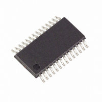
DS3882E+C Maxim Integrated Products, DS3882E+C Datasheet - Page 12

DS3882E+C
Manufacturer Part Number
DS3882E+C
Description
IC CCFL CNTRLR DUAL 28TSSOP
Manufacturer
Maxim Integrated Products
Type
CCFL Controllerr
Datasheet
1.DS3882EC.pdf
(31 pages)
Specifications of DS3882E+C
Frequency
40 ~ 100 kHz
Current - Supply
12mA
Voltage - Supply
4.75 V ~ 5.25 V
Operating Temperature
-40°C ~ 105°C
Package / Case
28-TSSOP
Maximum Operating Temperature
+ 105 C
Mounting Style
SMD/SMT
Minimum Operating Temperature
- 40 C
Lead Free Status / RoHS Status
Lead free / RoHS Compliant
Current - Output
-
Lead Free Status / Rohs Status
Lead free / RoHS Compliant
Other names
Q3390330
non-zero PWM code to the BPWM register disables the
BRIGHT pin and enables I
Setting the 7-bit PWM code to 0000001b causes the
DS3882 to operate with the minimum burst duty cycle,
while a setting of 1111111b causes a 100% burst duty
cycle. For settings between these two codes, the duty
cycle varies linearly between the minimum and 100%.
Analog dimming changes the brightness by increasing
or decreasing the lamp current. The DS3882 accom-
plishes this by making small shifts to the lamp regula-
tion voltage, V
only possible by software communication with the lower
five bits (LC4–LC0) in the BLC register. This function is
not pin controllable. The default power-on state of the
LC bits is 00000b, which corresponds to 100% of the
nominal current level. Therefore on power-up, analog
dimming does not interfere with burst dimming func-
tionality if it is not desired. Setting the LC bits to 11111b
reduces the lamp current to 35% of its nominal level. For
LC values between 11111b and 00000b, the lamp cur-
rent varies linearly between 35% and 100% of nominal.
The DS3882 can generate its own lamp frequency
clock internally (set LFSS = 0 in CR1), which can then
be sourced to other DS3882s if required, or the lamp
clock can be supplied from an external source (set
LFSS = 1 in CR1). When the lamp clock is internally
generated, the frequency (40kHz to 100kHz) is set by
Dual-Channel Automotive CCFL Controller
Figure 3. DPWM Source Configuration Options
12
CONTROL VOLTAGE
ANALOG DIMMING
SIGNAL
DPWM
____________________________________________________________________
22.5Hz TO 440Hz
EXTERNAL RESISTOR
LRT
SETS DPWM RATE
(see Figure 2). Analog dimming is
RESISTOR-SET DIMMING CLOCK
0.5V
Lamp Frequency Configuration
2
2.0V
C burst dimming control.
Analog Dimming
POSC
BRIGHT
PSYNC
an external resistor at the LOSC. In this case, the
DS3882 can act as a lamp frequency source because
the lamp clock is output at the LSYNC I/O pin for
synchronizing any other DS3882s configured as lamp
frequency receivers. While DS3882 is sourcing lamp
frequency to other DS3882’s and spread-spectrum
modulation or frequency step features are enabled, the
LSYNC output is not affected by either EMI suppression
features. The DS3882 acts as a lamp frequency receiv-
er when the lamp clock is supplied externally. In this
case, a 40kHz to 100kHz clock must be supplied at the
LSYNC I/O. The external clock can originate from the
LSYNC I/O of a DS3882 configured as a lamp frequency
source or from some other source.
Figure 4. DPWM Receiver Configuration
DPWM CLOCK
EXTERNAL
SIGNAL
DPWM
CONTROL VOLTAGE
ANALOG DIMMING
SIGNAL
DPWM
22.5Hz TO 440Hz
22.5Hz TO 440Hz
22.5Hz to 440Hz
DPWM RECEIVER
0.5V
EXTERNAL DIMMING CLOCK
2.0V
BRIGHT
PSYNC
POSC
BRIGHT
PSYNC
POSC


