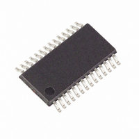
DS3882E+C Maxim Integrated Products, DS3882E+C Datasheet - Page 16

DS3882E+C
Manufacturer Part Number
DS3882E+C
Description
IC CCFL CNTRLR DUAL 28TSSOP
Manufacturer
Maxim Integrated Products
Type
CCFL Controllerr
Datasheet
1.DS3882EC.pdf
(31 pages)
Specifications of DS3882E+C
Frequency
40 ~ 100 kHz
Current - Supply
12mA
Voltage - Supply
4.75 V ~ 5.25 V
Operating Temperature
-40°C ~ 105°C
Package / Case
28-TSSOP
Maximum Operating Temperature
+ 105 C
Mounting Style
SMD/SMT
Minimum Operating Temperature
- 40 C
Lead Free Status / RoHS Status
Lead free / RoHS Compliant
Current - Output
-
Lead Free Status / Rohs Status
Lead free / RoHS Compliant
Other names
Q3390330
Figure 8 shows a flowchart of how the DS3882 controls
and monitors each lamp. The steps are as follows:
1) Supply Check—The lamps do not turn on unless the
2) Strike Lamp—When both the DS3882 and the DC
3) Run Lamp—Once the lamp is struck, the DS3882
Dual-Channel Automotive CCFL Controller
16
DS3882 supply voltage is above 4.3V and the volt-
age at the supply voltage monitors, SVML and SVMH,
are respectively above 2.0V and below 2.0V.
inverter supplies are at acceptable levels, the
DS3882 attempts to strike each enabled lamp. The
DS3882 slowly ramps up the MOSFET gate duty
cycle until the lamp strikes. The controller detects
that the lamp has struck by detecting current flow in
the lamp, detected by the LCMn pin. If during the
strike ramp, the maximum allowable voltage is
reached on the OVDn pin, the controller stops
increasing the MOSFET gate duty cycle to keep from
overstressing the system. The DS3882 goes into a
fault handling state (step 4) if the lamp has not struck
after the timeout period as defined by the LST0 and
LST1 control bits in the SSP1 register. If an overvolt-
age event is detected during the strike attempt, the
DS3882 disables the MOSFET gate drivers and go
into the fault handling state.
adjusts the MOSFET gate duty cycle to optimize the
lamp current. The gate duty cycle is always con-
strained to keep the system from exceeding the
maximum allowable lamp voltage. The lamp current
sampling rate is user-selectable using the LSR0 and
____________________________________________________________________
4) Fault Handling—During fault handling, the DS3882
• V
• The SVML or SVMH thresholds are crossed.
• The PDN pin goes high.
• The PDNE software bit is written to a logic 1.
• The channel is disabled by the CH1D or CH2D
LSR1 bits in CR2. If lamp current ever drops below the
lamp out reference point for the period as defined by
the LST0 and LST1 control bits in the SSP1 register,
then the lamp is considered extinguished. In this case,
the MOSFET gate drivers are disabled and the device
moves to the fault handling stage.
performs an optional (user-selectable) automatic
retry to attempt to clear all faults except a lamp over-
current. The automatic retry makes 14 additional
attempts to rectify the fault before declaring the
channel in a fault state and permanently disabling
the channel. Between each of the 14 attempts, the
controller waits 1024 lamp cycles. In the case of a
lamp overcurrent, the DS3882 instantaneously
declares the channel to be in a fault state and per-
manently disables the channel. The DS3882 can be
configured to disable all channels if one or more
channels enter a fault state or it can be configured to
disable only the channel where the fault occurred.
Once a fault state is entered, the channel remains in
that state until one of the following occurs:
control bit.
CC
drops below the UVLO threshold.


