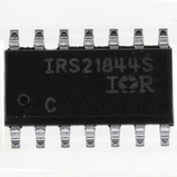
IRS21844SPBF International Rectifier, IRS21844SPBF Datasheet - Page 8

IRS21844SPBF
Manufacturer Part Number
IRS21844SPBF
Description
IC DRIVER HALF-BRIDGE 14-SOIC
Manufacturer
International Rectifier
Datasheet
1.IRS2184STRPBF.pdf
(30 pages)
Specifications of IRS21844SPBF
Configuration
Half Bridge
Input Type
Non-Inverting
Delay Time
680ns
Current - Peak
1.9A
Number Of Configurations
1
Number Of Outputs
2
High Side Voltage - Max (bootstrap)
600V
Voltage - Supply
10 V ~ 20 V
Operating Temperature
-40°C ~ 125°C
Mounting Type
Surface Mount
Package / Case
14-SOIC (3.9mm Width), 14-SOL
Lead Free Status / RoHS Status
Lead free / RoHS Compliant
www.irf.com
Tolerant to Negative V
A common problem in today’s high-power switching converters is the transient response of the switch
node’s voltage as the power switches transition on and off quickly while carrying a large current. A typical
half bridge circuit is shown in Figure 6; here we define the power switches and diodes of the inverter.
If the high-side switch (e.g., Q1 in Figures 7 and 8) switches off, while the phase current is flowing to a
load, a current commutation occurs from high-side switch (Q1) to the diode (D2) in parallel with the low-
side switch of the same inverter leg. At the same instance, the voltage node V
DC bus voltage to the negative DC bus voltage.
Also when the phase current flows from the load back to the inverter (see Figures 9 and 10), and Q4
switches on, the current commutation occurs from D3 to Q4. At the same instance, the voltage node, V
swings from the positive DC bus voltage to the negative DC bus voltage.
Figure 7: Q1 conducting
OFF
ON
Q1
Q2
DC+ BUS
V
DC- BUS
S 1
S
Transients
D2
I
U
Voltage
Figure 6: Half Bridge Circuit
Input
DC+ BUS
DC- BUS
IRS2184/IRS21844(S)PbF
Q1
Q2
V
S
D1
D2
Load
To
S1
, swings from the positive
Figure 8: D2 conducting
OFF
OFF
Q1
Q2
DC+ BUS
V
DC- BUS
S1
D1
D2
I
U
S2
,
8


