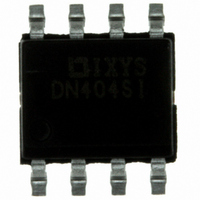
IXDN404SI IXYS, IXDN404SI Datasheet - Page 5

IXDN404SI
Manufacturer Part Number
IXDN404SI
Description
IC MOSFET DRVR LS 4A DUAL 8-SOIC
Manufacturer
IXYS
Type
Low Side Gate Driverr
Datasheet
1.IXDF404SI.pdf
(11 pages)
Specifications of IXDN404SI
Configuration
Low-Side
Input Type
Non-Inverting
Delay Time
36ns
Current - Peak
4A
Number Of Configurations
2
Number Of Outputs
2
Voltage - Supply
4.5 V ~ 35 V
Operating Temperature
-55°C ~ 125°C
Mounting Type
Surface Mount
Package / Case
8-SOIC
Number Of Drivers
2
Driver Configuration
Non-Inverting
Driver Type
Low Side
Input Logic Level
CMOS/TTL
Rise Time
18ns
Fall Time
17ns
Operating Supply Voltage (max)
35V
Peak Output Current
4mA
Output Resistance
1.5/2Ohm
Operating Supply Voltage (min)
4.5V
Operating Supply Voltage (typ)
18V
Turn Off Delay Time
39fs
Turn On Delay Time (max)
40ps
Operating Temp Range
-55C to 125C
Operating Temperature Classification
Military
Mounting
Surface Mount
Pin Count
8
Package Type
SOIC
Supply Voltage (min)
4.5 V
Supply Current
3 mA
Maximum Operating Temperature
+ 125 C
Mounting Style
SMD/SMT
Minimum Operating Temperature
- 55 C
Output Current
4 A
For Use With
EVDN404 - BOARD EVALUATION IXDN404
Lead Free Status / RoHS Status
Lead free / RoHS Compliant
High Side Voltage - Max (bootstrap)
-
Lead Free Status / Rohs Status
Compliant
Available stocks
Company
Part Number
Manufacturer
Quantity
Price
Company:
Part Number:
IXDN404SI
Manufacturer:
2002+
Quantity:
6 221
Part Number:
IXDN404SI
Manufacturer:
IXYS/艾赛斯
Quantity:
20 000
Company:
Part Number:
IXDN404SI-16
Manufacturer:
IXYS
Quantity:
4 899
Part Number:
IXDN404SIA
Manufacturer:
IXYS/艾赛斯
Quantity:
20 000
Company:
Part Number:
IXDN404SIA-16
Manufacturer:
IXYS
Quantity:
5 787
Pin Description
Figure 4 - Characteristics Test Diagram
CAUTION: These devices are sensitive to electrostatic discharge; follow proper ESD procedures when
handling and assembling this component.
SYMBOL
OUT B
OUT A
GND
VCC
IN A
IN B
10uF
25V
Vcc
B Channel Output
A Channel Output
A Channel Input
B Channel Input
Supply Voltage
FUNCTION
Ground
A Channel Input signal-TTL or CMOS compatible.
The system ground pin. Internally connected to all circuitry, this pin provides
ground reference for the entire chip. This pin should be connected to a low
noise analog ground plane for optimum performance.
B Channel Input signal-TTL or CMOS compatible.
B Channel Driver output. For application purposes, this pin is connected via
a resistor to a gate of a MOSFET/IGBT.
Positive power-supply voltage input. This pin provides power to the entire
chip. The range for this voltage is from 4.5V to 35V.
A Channel Driver output. For application purposes, this pin is connected via
a resistor to a gate of a MOSFET/IGBT.
1
3
4
2
In B
NC
Gnd
In A
5
Agilent 1147A
Current Probe
Out A
Out B
1800 pF
DESCRIPTION
Vcc
NC
6
5
8
7
IXDN404 / IXDI404 / IXDF404
1800 pF
Agilent 1147A
Current Probe


