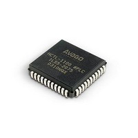
HCTL-1101 Avago Technologies US Inc., HCTL-1101 Datasheet - Page 36

HCTL-1101
Manufacturer Part Number
HCTL-1101
Description
IC MOTION CONTROL GP 40DIP
Manufacturer
Avago Technologies US Inc.
Datasheet
1.HCTL-1101.pdf
(40 pages)
Specifications of HCTL-1101
Applications
DC Motor Controller, Stepper Motor Controller
Voltage - Supply
4.75 V ~ 5.25 V
Operating Temperature
-20°C ~ 85°C
Mounting Type
Through Hole
Package / Case
40-DIP (0.600", 15.24mm)
Lead Free Status / RoHS Status
Lead free / RoHS Compliant
Current - Output
-
Number Of Outputs
-
Voltage - Load
-
Lead Free Status / Rohs Status
Lead free / RoHS Compliant
Available stocks
Company
Part Number
Manufacturer
Quantity
Price
Part Number:
HCTL-1101
Manufacturer:
AVAGO/安华高
Quantity:
20 000
Company:
Part Number:
HCTL-1101-PLC
Manufacturer:
Avago Technologies US Inc.
Quantity:
10 000
Figure 14. Trapezoidal Profile Mode.
The internal profile generator produces a position profile
using the present Command Position (R0CH-R0EH) as the
starting point and the Final Position (R2BH-R29H) as the
end point.
Once the desired data is entered, the user sets flag F0 in
the Flag register (R00H) to commence motion (if the HCTL-
1101 is already in Position Control mode).
When the profile generator sends the last position com-
mand to the Command Position registers to complete the
trapezoidal move, the controller clears flag F0. The HCTL-
1101 then automatically goes to Position Control mode
with the final position of the trapezoidal move as the com-
mand position.
When the HCTL-1101 clears flag F0 it does NOT indicate
that the motor and encoder are at the final position NOR
that the motor and encoder have stopped. The flag indi-
cates that the command profile has finished. The motor
and encoder’s true position can only be determined by
reading the Actual Position registers. The only way to de-
termine if the motor and encoder have stopped is to read
the Actual Position registers at successive intervals.
36
The status of the Profile flag can be monitored both in the
Status register (R07) and at the external Profile pin at any
time. While the Profile flag is high NO new command data
should be sent to the controller.
Each sample time, the internal profile generator uses the
information which the user has programmed into the
Maximum Velocity register (R28H), the Command Accel-
eration registers (R27H and R26H), and the Final Position
registers (R2BH, R2AH, and R29H) to determine the value
which will be automatically loaded into the Command
Position registers (R0EH, R0DH, and R0CH). After the new
command position has been generated, the difference
between the value in the Actual Position registers (R12H,
R13H, and R14H) and the new value in the Command Posi-
tion registers is calculated as the new position error. This
new position error is used by the full digital compensa-
tion filter to compute a new motor command output for
the sample time. (The register block diagram in Figure 3
further shows how the internal profile generator works in
Trapezoidal Profile mode.)


