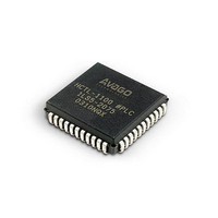
HCTL-1101 Avago Technologies US Inc., HCTL-1101 Datasheet - Page 38

HCTL-1101
Manufacturer Part Number
HCTL-1101
Description
IC MOTION CONTROL GP 40DIP
Manufacturer
Avago Technologies US Inc.
Datasheet
1.HCTL-1101.pdf
(40 pages)
Specifications of HCTL-1101
Applications
DC Motor Controller, Stepper Motor Controller
Voltage - Supply
4.75 V ~ 5.25 V
Operating Temperature
-20°C ~ 85°C
Mounting Type
Through Hole
Package / Case
40-DIP (0.600", 15.24mm)
Lead Free Status / RoHS Status
Lead free / RoHS Compliant
Current - Output
-
Number Of Outputs
-
Voltage - Load
-
Lead Free Status / Rohs Status
Lead free / RoHS Compliant
Available stocks
Company
Part Number
Manufacturer
Quantity
Price
Part Number:
HCTL-1101
Manufacturer:
AVAGO/安华高
Quantity:
20 000
Company:
Part Number:
HCTL-1101-PLC
Manufacturer:
Avago Technologies US Inc.
Quantity:
10 000
OE low enables the internal outputs latch onto the exter-
nal bus. The OE signal and the internal output latch allow
the I/O port to be flexible and avoid bus conflicts during
read operations.
It is important that the host microprocessor does not
attempt to perform too many I/O operations in a single
sample time of the HCTL-1101. Each I/O operation inter-
rupts the execution of the HCTL-1101’s internal code for
1 clock cycle.
Although extra clock cycles have been allotted in each
sample time for I/O operations, the number of extra cycles
is reduced as the value programmed into the Sample Tim-
er register (R0FH) is reduced.
Table 5 shows the maximum number of I/O operations al-
lowed under the given conditions.
The number of external clock cycles available for I/O oper-
ations in any of the four control modes can be increased by
increasing the value in the Sample Timer register (R0FH).
For every unit increase in the Sample Timer register (R0FH)
Table 5. Maximum Number of I/O Allowed
38
above the minimums shown in Table 5 the user may per-
form 16 additional I/O operations per sample time.
Interfacing the HCTL-1101 to Amplifiers and Motors
The Motor Command port is the ideal interface to an 8-
bit DAC, configured for bipolar output. The data written to
the 8-bit Motor Command port by the control algorithms
is the internally computed 2’s-complement motor com-
mand with an 80H offset added. This allows direct inter-
facing to a DAC. Figure 16 shows a typical DAC interface
to the HCTL-1101. An inexpensive DAC, such as MC1408
or equivalent, has its digital inputs directly connected to
the Motor Command port. The DAC pro-duces an output
current which is converted to a voltage by an operational
amplifier. RO and RG control the analog offset and gain.
The circuit is easily adjusted for +5 V to –5 V operations by
first writing 80H to R08H and adjusting RO for 0 V output.
Then FFH is written to R08H and R is Adjusted until the
output is 5 V. Note that 00H in R08H corresponds to –5 V
out. Figure 17 shows an example of how to interface the
HCTL-1101 to an H-bridge amplifier. An H-bridge ampli-
fier allows bipolar motor operation with a unipolar power
supply.


