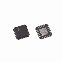
ISL6271ACRZ Intersil, ISL6271ACRZ Datasheet - Page 13

ISL6271ACRZ
Manufacturer Part Number
ISL6271ACRZ
Description
IC REG PMIC 1BUCK 2LDO 20QFN
Manufacturer
Intersil
Datasheet
1.ISL6271ACRZ-T.pdf
(16 pages)
Specifications of ISL6271ACRZ
Applications
Processor
Current - Supply
380µA
Voltage - Supply
2.76 V ~ 5.5 V
Operating Temperature
-25°C ~ 85°C
Mounting Type
Surface Mount
Package / Case
20-QFN
Rohs Compliant
Yes
Lead Free Status / RoHS Status
Lead free / RoHS Compliant
Available stocks
Company
Part Number
Manufacturer
Quantity
Price
Part Number:
ISL6271ACRZ
Manufacturer:
INTERSIL
Quantity:
20 000
Part Number:
ISL6271ACRZ-T
Manufacturer:
INTERSIL
Quantity:
20 000
Company:
Part Number:
ISL6271ACRZT
Manufacturer:
INFN
Quantity:
5 195
Light Load Operation - DCM
A light load is defined when the output inductor ripple current
reaches zero before the next switching cycle. Under this
condition, the ISL6271A synchronous rectifier will turn off
emulating a diode to prevent negative inductor current. As
explained below, the switching frequency and losses
associated with turning on the synchronous rectifier will be
reduced to enhance the low current efficiency. The top
waveform in Figure 22 shows the phase voltage in DCM.
The middle waveforms include the error amplifier voltage,
ripple capacitor voltage and the boundaries of the hysteresis
comparator which track the EA output. The waveform at the
bottom is representative of the inductor current. Notice that
in a switching cycle the inductor current rises as the upper
P-MOSFET turns on, falls when the lower N-MOSFET turns
on, and stays at zero after the current reaches zero as a
result of diode emulation.
To understand the ISL6271A light load operation, look
carefully at the waveforms in the middle of Figure 22. Notice
that the voltage across the ripple capacitor, VRP, has a
minimum clamp voltage (typically 0.4V), and that the Error
Amplifier can go below this voltage (typically clamped to
0.2V). In DCM, the voltage across ripple capacitor will be
discharged each cycle to the clamp voltage. While the lower
hysteresis is below this voltage, the ripple capacitor will
remain clamped keeping the upper P-MOSFET off. As the
EA voltage increases so too will the lower threshold of the
hysteresis window until it reaches the ripple capacitor clamp
voltage (VCLMP). At this point, the upper FET will be
enabled and will turn on. The lighter the load, the lower the
error amplifier output is, and the longer the ripple capacitor
voltage stays at the VCLMP voltage. This results in a phase
node switching frequency that is proportional to load current
(that is, lower switching losses and higher efficiency at
lighter loads). In DCM the switching frequency will be lower
than in a heavy load, CCM.
VCMP
VPH
VEA
VRP
ILO
CLAMPED VRP = > LOWER HYS
FIGURE 22. SRR IN DCM
CLAMPED VRP> LOWER HYS
13
ISL6271A
A load transition from full load to no load will result in a finite
period of time during which the error amplifier settles to a
new steady state condition. As illustrated in Figure 23, the
SSR architecture inherent to the ISL6271A responds within
6µs of the mode change, slewing the error amplifier output
below the clamped ripple capacitor voltage and preventing
the upper FET from turning on. Prior to reaching the new
stability point, the phase node applies four phase pulses
before the controller forces the output voltage to the
prescribed regulation point. Once the output falls below the
reference voltage the controller then pumps up the output
voltage and enters its steady state DCM. Mode changes that
take the converter from CCM into DCM will have much
higher output voltage spike than a load step that remains in
CCM. Compared with competitive solutions the ISL6271A
responds very well during this severe mode change and it is
more than sufficient to meet Vcore tolerance specifications
as required by Intel.
Transition Between Light load and Heavy Load
Unlike most control topologies that require two sets of
circuits to control the light and heavy load operation, the
SRR control naturally switches between heavy and light load
with the same control circuit. As the load gets lighter, the
feedback forces the error amplifier output to a lower voltage
and when the lower threshold of the hysteresis window is
lower than VCLMP, light load operation begins. The scope
shot in Figure 24 illustrates a mode transition from a DCM
(10mA load current) to CCM (170mA) with trace 4 (GRN)
being the command pulse that initiates the mode change.
Prior to the load step, and while the converter is in DCM, the
ripple voltage is approximately 10mV and the ripple
frequency is 125kHz. In CCM, the converter operates at a
frequency of approximately 10X that of DCM and the ripple
is reduced by more than a factor of two.
LOOP CLOSES 6µs AFTER MODE CHANGE
CCM
FIGURE 23. CCM TO DCM MODE
PHASE PULSES BEFORE LOOP IS CLOSED
DCM
FN9171.1


