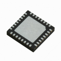
IR3529MTRPBF International Rectifier, IR3529MTRPBF Datasheet - Page 8

IR3529MTRPBF
Manufacturer Part Number
IR3529MTRPBF
Description
IC CTRL XPHASE CPU/ASIC 20-MLPQ
Manufacturer
International Rectifier
Series
XPhase3™r
Datasheet
1.IR3529MTRPBF.pdf
(22 pages)
Specifications of IR3529MTRPBF
Applications
Processor
Current - Supply
2mA
Voltage - Supply
8 V ~ 16 V
Operating Temperature
0°C ~ 125°C
Mounting Type
Surface Mount
Package / Case
*
Package
20-Lead MLPQ
Circuit
X-Phase Phase IC
Iout (a)
4.0A Gate Driver
Pbf
PbF Option Available
Lead Free Status / RoHS Status
Lead free / RoHS Compliant
Other names
IR3529MTRPBFTR
SYSTEM THEORY OF OPERATION
System Description
The system consists of one control IC and a scalable array of phase converters, each requiring one phase IC. The
control IC communicates with the phase ICs using three digital buses, i.e., CLOCK, PHSIN, PHSOUT and three analog
buses, i.e., DAC, EA, and IOUT. The digital buses are responsible for switching frequency determination and accurate
phase timing control without any external components. The analog buses are used for PWM control and current
sharing between interleaved phases. The control IC incorporates all the system functions, i.e., VID, CLOCK signals,
error amplifier, fault protections, current monitor, etc. The Phase IC implements the functions required by the converter
of each phase, i.e., the gate drivers, PWM comparator and latch, over-voltage protection, phase disable circuit, current
sensing and sharing, etc.
PWM Control Method
The PWM block diagram of the XPhase3
trailing edge modulation is used. A high-gain and wide-bandwidth voltage type error amplifier is implemented in the
controller’s design to achieve a fast voltage control loop. Input voltage is sensed by the phase ICs to provide feed-
forward control. The feed-forward control compensates the ramp slope based on the change in input voltage. The input
voltage can change due to variations in the silver box output voltage or due to the wire and PCB-trace voltage drop
related to changes in load current.
Page 8 of 22
IVSETPT
NO. OF ACTIVE PHASES MONITOR
VDRP
AMP
CONTROL IC
CLOCK GENERATOR
+
-
REMOTE SENSE
AMPLIFIER
+
-
IROSC
ERROR
AMPLIFIER
Compensation
Thermal
VDAC
VDAC
+
-
VN
VSETPT
IMON
IIN
VDRP
PHSOUT
PHSIN
PSI
CLKOUT
SHIFT
VO
VDAC
LGND
EAOUT
FB
RVSETPT
RTHRM
RCOMP
CCOMP
RFB1
CFB1
RDRP1
CDRP
TM
GATE DRIVE
VOLTAGE
RFB
RDRP
architecture is shown in Figure 1. Feed-forward voltage mode control with
Figure 1: PWM Block Diagram
PHSOUT
PHSOUT
PHSIN
ISHARE
CLKIN
ISHARE
DACIN
DACIN
EAIN
CLKIN
EAIN
PHSIN
ILL
ILL
CLK
D
CLK
D
SHARE ADJUST
VID6
SHARE ADJUST
VID6
Q
Q
1
1
AMPLIFIER
AMPLIFIER
VID6
VID6
VID6
VID6
2
2
VID6
VID6
PWM COMPARATOR
VID6
VID6
PWM COMPARATOR
VID6
VID6
LATCH
LATCH
VID6
PHASE IC
VID6
&
PHASE IC
&
VID6 VID6
VID6
VID6
VID6
BRAKING
BODY
BRAKING
BODY
VID6
VID6
VID6
VID6
VID6
VID6
VID6
VID6
VID6
VID6
GENERATION
VID6
VID6
GENERATION
SHIFT
PULSE
+
SHIFT
PULSE
+
VID6
+
+
PSI# COMPARATOR
8 COUNT DELAY
VID6
PSI# COMPARATOR
8 COUNT DELAY
&
&
AMPLIFIER
AMPLIFIER
VID6
CURRENT
VID6
CURRENT
SENSE
VID6
SENSE
VID6
OFF
OFF
OFF
OFF
VID6
VID6
VID6
VID6
VID6
VID6
VID6
VID6
CSIN+
CSIN-
PSI
VCC
VCCH
GATEH
SW
VCCL
GATEL
PGND
SHIFT
VCCL
GATEL
CSIN-
VCC
VCCH
PSI
SHIFT
CSIN+
GATEH
SW
PGND
February 12, 2010
CCS
CCS
RCS
RCS
CBST
CBST
IR3529
COUT
PSI#
SHIFT
VIN
VOSNS+
VOUT
GND
VOSNS-


