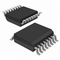
NE1617ADS,112 NXP Semiconductors, NE1617ADS,112 Datasheet - Page 11

NE1617ADS,112
Manufacturer Part Number
NE1617ADS,112
Description
IC TEMP MONITOR 16SSOP
Manufacturer
NXP Semiconductors
Datasheet
1.NE1617ADS118.pdf
(27 pages)
Specifications of NE1617ADS,112
Function
Temp Monitoring System (Sensor)
Topology
ADC, Multiplexer, Register Bank
Sensor Type
External & Internal
Sensing Temperature
-55°C ~ 125°C, External Sensor
Output Type
SMBus™
Output Alarm
Yes
Output Fan
No
Voltage - Supply
3 V ~ 5.5 V
Operating Temperature
-55°C ~ 125°C
Mounting Type
Surface Mount
Package / Case
16-QSOP
Temperature Sensor Function
Temp Sensor
Interface Type
Serial (2-Wire)
Operating Temperature (min)
0C
Operating Temperature (max)
125C
Operating Temperature Classification
Military
Operating Supply Voltage (min)
3V
Operating Supply Voltage (typ)
3.3/5V
Operating Supply Voltage (max)
5.5V
Lead Free Status / RoHS Status
Lead free / RoHS Compliant
Other names
935268119112
NE1617ADS
NE1617ADS
NE1617ADS
NE1617ADS
NXP Semiconductors
1.
NE1617A_4
Product data sheet
The NE1617A implements the collision arbitration function per System Management Bus Specification Revision 1.1 , dated
December 11, 1998, which conforms to standard I
specification and user manual” .
8.4 Power-up default condition
8.5 Fault detection
the Alert Response byte from the Alert Response Address, which is a special slave
address to the SMBus. The ALERT output cannot be reset by reading the device status
register.
The device was designed to accommodate the Alert interrupt detection capability of the
SMBus.
identify the slave device which has caused the Alert interrupt. The 7-bit Alert response
slave address is 0001 100 and the Alert response byte reflects the slave address of the
device which has caused Alert interrupt. Bit assignments of the Alert response byte are
listed in
response slave address unless the fault condition persists.
Table 9.
Upon power-up reset (power is switched off-on), the NE1617A goes into this default
condition:
The NE1617A has a fault detector to the diode connection. The connection is checked
when a conversion is initiated and the proper flags are set if the fault condition has
occurred.
Table 10.
Bit
7 (MSB)
6
5
4
3
2
1
0 (LSB)
D+ and D
opened
shorted
•
•
•
•
Interrupt latch is cleared, the ALERT output is pulled HIGH by the external pull-up
resistor.
The auto-conversion rate is at 0.25 Hz; conversion rate data is 02h.
Temperature limits for both channels are +127 C for high limit, and 55 C for low
limit.
Command pointer register is set to ‘00’ for quickly reading the RIT.
1
Table
Basically, the SMBus provides Alert response interrupt pointers in order to
Symbol
ADD7
ADD6
ADD5
ADD4
ADD3
ADD2
ADD1
1
Alert response (Alert response address 0001 100) bit description
Fault detection
9. The ALERT output will be reset to HIGH state upon reading the Alert
ALERT output
LOW
LOW
2
C-bus arbitration as described in NXP document UM10204, “I
Rev. 04 — 30 July 2009
Description
indicate address B6 of alerted device
indicate address B5 of alerted device
indicate address B4 of alerted device
indicate address B3 of alerted device
indicate address B2 of alerted device
indicate address B1 of alerted device
indicate address B0 of alerted device
logic 1
Temperature monitor for microprocessor systems
RET data storage
127 C
127 C
Status set flag
B2 and B4
B4
NE1617A
© NXP B.V. 2009. All rights reserved.
2
C-bus
11 of 27


