IR3637STRPBF International Rectifier, IR3637STRPBF Datasheet - Page 11
IR3637STRPBF
Manufacturer Part Number
IR3637STRPBF
Description
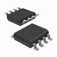
IC SYNC BUCK REGULATOR 8 SOIC
Manufacturer
International Rectifier
Datasheet
1.IR3637STRPBF.pdf
(21 pages)
Specifications of IR3637STRPBF
Pwm Type
Voltage Mode
Number Of Outputs
1
Frequency - Max
440kHz
Duty Cycle
85%
Voltage - Supply
4.5 V ~ 14 V
Buck
Yes
Boost
No
Flyback
No
Inverting
No
Doubler
No
Divider
No
Cuk
No
Isolated
No
Operating Temperature
0°C ~ 125°C
Package / Case
8-SOIC (3.9mm Width)
Frequency-max
440kHz
Output Current
15A
Frequency
400kHz
Supply Voltage Range
4.5V To 5.5V
Digital Ic Case Style
SOIC
No. Of Pins
8
Operating Temperature Range
0°C To +125°C
Termination Type
SMD
Rohs Compliant
Yes
Filter Terminals
SMD
Controller Type
PWM
For Use With
IRPP3637-12A - KIT REF DES 12A 1PH SYNC BUCKIRDC3637 - BOARD EVAL SYNC BUCK REGULATOR
Lead Free Status / RoHS Status
Lead free / RoHS Compliant
Other names
IR3637STRPBF
IR3637STRPBFTR
IR3637STRPBFTR
Available stocks
Company
Part Number
Manufacturer
Quantity
Price

Part Number:
IR3637STRPBF
Manufacturer:
IR
Quantity:
20 000


6) Place second pole at the ESR zero.
7) Place second zero around the resonant frequency.
8) Use equation (1) to calculate R
These design rules will give a crossover frequency ap-
proximately one-tenth of the switching frequency. The
higher the band width, the potentially faster the load tran-
sient speed. The gain margin will be large enough to
provide high DC-regulation accuracy (typically -5dB to -
12dB). The phase margin should be greater than 45 for
overall stability.
Based on the frequency of the zero generated by ESR
versus crossover frequency, the compensation type can
be different. The table below shows the compensation
type and location of crossover frequency.
Type II (PI)
Type III (PID)
Method A
Type III (PID)
Method B
Detail information is dicussed in application Note AN-
1043 which can be downloaded from the IR Web-Site.
All design should be tested for stability to verify the cal-
culated values.
Rev. 1.1
06/16/05
Compensator
Table - The compensation type and location of zero
F
R
Check if R
If R
F
R
R
Type
P2
Z2
8
6
5
=
=
=
= F
= F
8
is too small, increase R
2π × C
V
2π × C
ESR
LC
OUT
V
REF
8
- V
>
Crossover Frequency
1
crossover frequency.
10
F
F
F
1
REF
10
g
Location of Zero
LC
LC
LC
1
× F
m
× F
< F
< F
< F
× R
Z2
O
P2
ESR
O
< f
(F
< F
6
- R
< F
O
S
)
ESR
/2 < F
8
O
7
< f
< f
and start from step 2.
S
S
5
ESR
/2
/2
.
Electrolytic,
Capacitor
Tantalum,
Tantalum
Ceramic
Ceramic
Typical
Output
www.irf.com
Layout Consideration
The layout is very important when designing high fre-
quency switching converters. Layout will affect noise
pickup and can cause a good design to perform with
less than expected results.
Start to place the power components, make all the con-
nection in the top layer with wide, copper filled areas.
The inductor, output capacitor and the MOSFET should
be close to each other as possible. This helps to reduce
the EMI radiated by the power traces due to the high
switching currents through them. Place input capacitor
directly to the drain of the high-side MOSFET, to reduce
the ESR replace the single input capacitor with two par-
allel units. The feedback part of the system should be
kept away from the inductor and other noise sources,
and be placed close to the IC. In multilayer PCB use
one layer as power ground plane and have a control cir-
cuit ground (analog ground), to which all signals are ref-
erenced. The goal is to localize the high current path to
a separate loop that does not interfere with the more
sensitive analog control function. These two grounds
must be connected together on the PC board layout at a
single point.
IR3637SPBF
11
Related parts for IR3637STRPBF
Image
Part Number
Description
Manufacturer
Datasheet
Request
R

Part Number:
Description:
1% Accurate Synchronous Pwm Controller
Manufacturer:
International Rectifier Corp.
Datasheet:
Part Number:
Description:
SCHOTTKY RECTIFIER
Manufacturer:
International Rectifier Corp.
Datasheet:
Part Number:
Description:
SCHOTTKY RECTIFIER
Manufacturer:
International Rectifier Corp.
Datasheet:
Part Number:
Description:
SCHOTTKY RECTIFIER
Manufacturer:
International Rectifier Corp.
Datasheet:
Part Number:
Description:
SCHOTTKY RECTIFIER
Manufacturer:
International Rectifier Corp.
Datasheet:
Part Number:
Description:
SCHOTTKY RECTIFIER
Manufacturer:
International Rectifier Corp.
Datasheet:
Part Number:
Description:
SCHOTTKY RECTIFIER
Manufacturer:
International Rectifier Corp.
Datasheet:
Part Number:
Description:
SCHOTTKY RECTIFIER
Manufacturer:
International Rectifier Corp.
Datasheet:
Part Number:
Description:
SCHOTTKY RECTIFIER
Manufacturer:
International Rectifier Corp.
Datasheet:
Part Number:
Description:
SCHOTTKY RECTIFIER
Manufacturer:
International Rectifier Corp.
Datasheet:
Part Number:
Description:
SCHOTTKY RECTIFIER
Manufacturer:
International Rectifier Corp.
Datasheet:
Part Number:
Description:
SCHOTTKY RECTIFIER
Manufacturer:
International Rectifier Corp.
Datasheet:
Part Number:
Description:
SCHOTTKY RECTIFIER
Manufacturer:
International Rectifier Corp.
Datasheet:
Part Number:
Description:
SCHOTTKY RECTIFIER
Manufacturer:
International Rectifier Corp.
Datasheet:
Part Number:
Description:
SCHOTTKY RECTIFIER
Manufacturer:
International Rectifier Corp.
Datasheet: