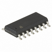
ISL6740IBZ Intersil, ISL6740IBZ Datasheet - Page 26

ISL6740IBZ
Manufacturer Part Number
ISL6740IBZ
Description
IC CTRLR PWM DBL-ENDED 16-SOIC
Manufacturer
Intersil
Datasheet
1.ISL6741IVZ.pdf
(29 pages)
Specifications of ISL6740IBZ
Pwm Type
Voltage Mode
Number Of Outputs
2
Frequency - Max
2MHz
Duty Cycle
100%
Voltage - Supply
9 V ~ 16 V
Buck
No
Boost
No
Flyback
No
Inverting
No
Doubler
No
Divider
No
Cuk
No
Isolated
No
Operating Temperature
-40°C ~ 105°C
Package / Case
16-SOIC (3.9mm Width)
Frequency-max
2MHz
Lead Free Status / RoHS Status
Lead free / RoHS Compliant
Available stocks
Company
Part Number
Manufacturer
Quantity
Price
Company:
Part Number:
ISL6740IBZ
Manufacturer:
Intersil
Quantity:
122
The actual loop gain and phase margin measured on the
ISL6740EVAL2Z demonstration board appear in Figures 26A
and 26B:
The only major discrepancies between the predicted
behavior and the measured results are the Q of the L-C filter
and the phase behavior above 60kHz. The actual Q appears
to be significantly less than predicted resulting in less gain
peaking and a less rapid phase shift near the resonant
frequency. This is most likely the result of neglecting other
losses in the converter’s output, such as the FET on
resistance, copper losses, and inductor resistance. The
phase discrepancy above 60kHz is not particularly relevant
to the loop performance since it occurs well above the cross
over frequency. The predicted behavior indicates a much
gentler drop off of phase than was observed in the measured
performance. The discrepancy was not investigated.
FIGURE 26B. MEASURE LOOP PHASE MARGIN
-135
225
180
135
-10
-20
-30
-40
-50
-45
-90
50
40
30
20
10
90
45
0
FIGURE 26A. MEASURED LOOP GAIN
0
0.1k
0.1k
FREQUENCY (Hz)
FREQUENCY (Hz)
1k
1k
26
10k
10k
100k
100k
ISL6740, 1SL6741
Performance
The major performance criteria for the converter are
efficiency and load regulation. These quantities are detailed
in Figures 27 and 28.
The efficiency, although very good, could be further
improved using a controlled SR method instead of using a
self-driven method with an auxiliary schottky diode. The
schottky diode conducts when the main switching FETs are
off. Its forward voltage drop is considerably larger than that
of the SR FETs and causes a measurable reduction in
efficiency. The effect becomes more significant as the input
voltage is increased due to the reduction of duty cycle (and
consequent increase in the OFF time).
FIGURE 28. LOAD REGULATION AT V
FIGURE 27. EFFICIENCY vs LOAD V
95
93
91
89
87
85
12.015
12.010
12.005
12.000
11.995
2
0
3
1
4
2
LOAD CURRENT (A)
LOAD CURRENT (A)
3
5
4
6
5
7
6
7
IN
8
IN
= 48V
8
= 48V
9
9
July 13, 2007
t
10
FN9111.4
10


