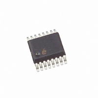
ISL6742AAZA-T Intersil, ISL6742AAZA-T Datasheet - Page 5

ISL6742AAZA-T
Manufacturer Part Number
ISL6742AAZA-T
Description
IC CTRLR PWM DBL ENDED 16-QSOP
Manufacturer
Intersil
Datasheet
1.ISL6742AAZA.pdf
(18 pages)
Specifications of ISL6742AAZA-T
Pwm Type
Voltage/Current Mode
Number Of Outputs
4
Frequency - Max
2MHz
Duty Cycle
100%
Voltage - Supply
9 V ~ 16 V
Buck
No
Boost
No
Flyback
No
Inverting
No
Doubler
No
Divider
No
Cuk
No
Isolated
No
Operating Temperature
-40°C ~ 105°C
Package / Case
16-QSOP
Frequency-max
2MHz
Lead Free Status / RoHS Status
Lead free / RoHS Compliant
Other names
ISL6742AAZA-TTR
Available stocks
Company
Part Number
Manufacturer
Quantity
Price
Company:
Part Number:
ISL6742AAZA-T
Manufacturer:
Intersil
Quantity:
2 000
Part Number:
ISL6742AAZA-T
Manufacturer:
INTERSIL
Quantity:
20 000
Electrical Specifications
Absolute Maximum Ratings
Supply Voltage, V
OUTxx . . . . . . . . . . . . . . . . . . . . . . . . . . . . . . . . GND - 0.3V to V
Signal Pins . . . . . . . . . . . . . . . . . . . . . . . GND - 0.3V to V
VREF . . . . . . . . . . . . . . . . . . . . . . . . . . . . . . . . . GND - 0.3V to 6.0V
Peak GATE Current . . . . . . . . . . . . . . . . . . . . . . . . . . . . . . . . . . 0.1A
Operating Conditions
Temperature Range . . . . . . . . . . . . . . . . . . . . . . . . .-40°C to +105°C
Supply Voltage Range (Typical). . . . . . . . . . . . . . . 9VDC to 16 VDC
CAUTION: Do not operate at or near the maximum ratings listed for extended periods of time. Exposure to such conditions may adversely impact product reliability and
result in failures not covered by warranty.
NOTES:
SUPPLY VOLTAGE
Supply Voltage
Start-Up Current, I
Operating Current, I
UVLO START Threshold
UVLO STOP Threshold
Hysteresis
REFERENCE VOLTAGE
Overall Accuracy
Long Term Stability
Operational Current (Source)
Operational Current (Sink)
Current Limit
CURRENT SENSE
Current Limit Threshold
CS to OUT Delay
Leading Edge Blanking (LEB) Duration
CS to OUT Delay + LEB
CS Sink Current Device Impedance
Input Bias Current
IOUT Sample and Hold Buffer Amplifier Gain
IOUT Sample and Hold VOH
IOUT Sample and Hold VOL
1. θ
2. All voltages are with respect to GND.
JA
is measured with the component mounted on a high effective thermal conductivity test board in free air. See Tech Brief TB379 for details.
DD
PARAMETER
DD
DD
. . . . . . . . . . . . . . . . . . . GND - 0.3V to +20.0V
5
Recommended operating conditions unless otherwise noted. Refer to “Functional Block Diagram” on page 2,
“Typical Application - Telecom Primary Side Control Half-Bridge Converter with Synchronous Rectification” on
page 3 and “Typical Application - High Voltage Input Secondary Side Control Full-Bridge Converter” on page 4.
9V < VDD < 20V, RTD = 10.0kΩ, CT = 470pF, T
Parameters with MIN and/or MAX limits are 100% tested at +25°C, unless otherwise specified. Temperature
limits established by characterization and are not production tested.
(Note 2)
VDD = 5.0V
R
I
T
VREF = 4.85V
VERR = VREF
Excl. LEB (Note 3)
(Note 3)
T
V
V
T
V
V
VREF
A
A
A
CS
CS
CS
CS
LOAD
= +125°C, 1000 hours (Note 3)
= +25°C
= +25°C
REF
= 1.1V
= 0.3V
= 1.00V, I
= 0.00V, I
= 0mA to 10mA
, C
TEST CONDITIONS
+ 0.3V
OUT
DD
LOAD
LOAD
ISL6742
= 0
= -300µA
= 10µA
Thermal Information
Thermal Resistance Junction to Ambient (Typical)
Maximum Junction Temperature . . . . . . . . . . . . . . .-55°C to +150°C
Maximum Storage Temperature Range . . . . . . . . . .-65°C to +150°C
Pb-Free Reflow Profile. . . . . . . . . . . . . . . . . . . . . . . . .see link below
16 Lead QSOP (Note 1). . . . . . . . . . . . . . . . . . . . . .
http://www.intersil.com/pbfree/Pb-FreeReflow.asp
A
= -40°C to +105°C, Typical values are at T
4.850
8.00
6.50
0.97
4.00
MIN
-1.0
-10
-15
3.9
50
5
-
-
-
-
-
-
-
-
-
5.000
TYP
8.75
7.00
1.75
1.00
4.09
175
7.5
35
70
3
-
-
-
-
-
-
-
-
-
5.150
MAX
-100
12.0
9.00
7.50
1.03
4.15
400
100
130
1.0
0.3
20
50
20
-
-
-
-
-
A
= +25°C.
October 31, 2008
θ
JA
UNITS
V/V
mA
mV
mA
mA
mA
µA
µA
100
ns
ns
ns
FN9183.2
V
V
V
V
V
V
Ω
V
V
(°C/W)


