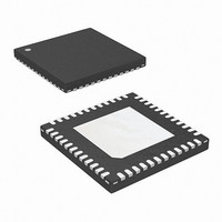
ISL6327IRZ-T Intersil, ISL6327IRZ-T Datasheet - Page 11

ISL6327IRZ-T
Manufacturer Part Number
ISL6327IRZ-T
Description
IC CTRLR PWM 6PHASE BUCK 48-QFN
Manufacturer
Intersil
Datasheet
1.ISL6327CRZ.pdf
(29 pages)
Specifications of ISL6327IRZ-T
Pwm Type
Voltage Mode
Number Of Outputs
1
Frequency - Max
275kHz
Duty Cycle
25%
Voltage - Supply
4.75 V ~ 5.25 V
Buck
Yes
Boost
No
Flyback
No
Inverting
No
Doubler
No
Divider
No
Cuk
No
Isolated
No
Operating Temperature
-40°C ~ 85°C
Package / Case
48-VQFN
Frequency-max
275kHz
Lead Free Status / RoHS Status
Lead free / RoHS Compliant
Available stocks
Company
Part Number
Manufacturer
Quantity
Price
Part Number:
ISL6327IRZ-T
Manufacturer:
INTERSIL
Quantity:
20 000
RMS input capacitor current. The single-phase converter
must use an input capacitor bank with twice the RMS current
capacity as the equivalent three-phase converter.
Figures 19, 20 and 21 in the section titled “Input Capacitor
Selection” on page 27 can be used to determine the input
capacitor RMS current based on the load current, the duty
cycle, and the number of channels. They are provided as
aids in determining the optimal input capacitor solution.
Figure 22 shows the single phase input-capacitor RMS
current for comparison.
PWM Modulation Scheme
The ISL6327 adopts Intersil's proprietary Active Pulse
Positioning (APP) modulation scheme to improve the
transient performance. APP control is a unique dual-edge
PWM modulation scheme with both PWM leading and
trailing edges being independently moved to provide the
best response to the transient loads. The PWM frequency,
however, is constant and set by the external resistor
between the FS pin and GND.
To further improve the transient response, the ISL6327 also
implements Intersil's proprietary Adaptive Phase Alignment
(APA) technique. APA, with sufficiently large load step
currents, can turn on all phases together.
With both APP and APA control, ISL6327 can achieve
excellent transient performance and reduce the demand on
the output capacitors.
Under the steady state conditions the operation of the
ISL6327 PWM modulator appears to be that of a
conventional trailing edge modulator. Conventional analysis
and design methods can therefore be used for steady state
and small signal operation.
PWM Operation
The timing of each converter is set by the number of active
channels. The default channel setting for the ISL6327 is six.
The switching cycle is defined as the time between PWM
pulse termination signals of each channel. The cycle time of
the pulse termination signal is the inverse of the switching
frequency set by the resistor between the FS pin and
ground. The PWM signals command the MOSFET drivers to
turn on/off the channel MOSFETs.
In the default 6-phase operation, the PWM2 pulse happens
1/6 of a cycle after PWM1, the PWM3 pulse happens 1/6 of
a cycle after PWM2, the PWM4 pulse happens 1/6 of a cycle
after PWM3, the PWM5 pulse happens 1/6 of a cycle after
PWM4, and the PWM6 pulse happens 1/6 of a cycle after
PWM5.
The ISL6327 works in 2, 3, 4, 5, or 6 phase configuration.
Connecting the PWM6 to VCC selects 5-phase operation
and the pulse times are spaced in 1/5 cycle increments.
Connecting the PWM5 to VCC selects 4-phase operation
and the pulse times are spaced in 1/4 cycle increments.
11
ISL6327
Connecting the PWM4 to VCC selects 3-phase operation
and the pulse times are spaced in 1/3 cycle increments.
Connecting the PWM3 to VCC selects 2-phase operation
and the pulse times are spaced in 1/2 cycle increments.
Switching Frequency
The switching frequency is determined by the selection of
the frequency-setting resistor, R
FS pin to GND (see the figures labelled Typical Applications
on page 4 and page 5). Equation 3 is provided to assist in
selecting the correct resistor value.
R
where f
Current Sensing
ISL6327 senses the current continuously for fast response.
ISL6327 supports inductor DCR sensing, or resistive
sensing techniques. The associated channel current sense
amplifier uses the ISEN inputs to reproduce a signal
proportional to the inductor current, I
I
regulation, and the overcurrent protection.
The internal circuitry, shown in Figures 3 and 4, represents
one channel of an N-channel converter. This circuitry is
repeated for each channel in the converter, but may not be
active depending on the status of the PWM3, PWM4,
PWM5, and PWM6 pins, as described in “PWM Operation”
on page 11.
INDUCTOR DCR SENSING
An inductor’s winding is characteristic of a distributed
resistance as measured by the DCR (Direct Current
Resistance) parameter. Consider the inductor DCR as a
separate lumped quantity, as shown in Figure 3. The
channel current I
pass through the DCR. Equation 4 shows the S-domain
(equivalent voltage across the inductor V
A simple RC network across the inductor extracts the DCR
voltage, as shown in Figure 3.
The voltage on the capacitor V
proportional to the channel current I
V
SEN
V
T
C
L
=
=
=
, is used for the current balance, the load-line
2.5X10
------------------------- - 600
I
⎛
⎝
-------------------------------------------------------------------- -
L
s
SW
f
⋅
⋅
SW
(
-------------
DCR
s L
is the switching frequency of each phase.
⋅
L
10
(
s RC
+
–
+
⋅
DCR
1
L
⎞
⎠
, flowing through the inductor, will also
⋅
+
(
)
DCR I
1
)
⋅
L
)
C
T
, can be shown to be
, which is connected from
L
L
, see Equation 5.
. The sensed current,
L
).
May 5, 2008
(EQ. 4)
(EQ. 5)
FN9276.4
(EQ. 3)


