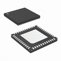
ISL6327IRZ-T Intersil, ISL6327IRZ-T Datasheet - Page 8

ISL6327IRZ-T
Manufacturer Part Number
ISL6327IRZ-T
Description
IC CTRLR PWM 6PHASE BUCK 48-QFN
Manufacturer
Intersil
Datasheet
1.ISL6327CRZ.pdf
(29 pages)
Specifications of ISL6327IRZ-T
Pwm Type
Voltage Mode
Number Of Outputs
1
Frequency - Max
275kHz
Duty Cycle
25%
Voltage - Supply
4.75 V ~ 5.25 V
Buck
Yes
Boost
No
Flyback
No
Inverting
No
Doubler
No
Divider
No
Cuk
No
Isolated
No
Operating Temperature
-40°C ~ 85°C
Package / Case
48-VQFN
Frequency-max
275kHz
Lead Free Status / RoHS Status
Lead free / RoHS Compliant
Available stocks
Company
Part Number
Manufacturer
Quantity
Price
Part Number:
ISL6327IRZ-T
Manufacturer:
INTERSIL
Quantity:
20 000
Functional Pin Description
VCC - Supplies the power necessary to operate the chip.
The controller starts to operate when the voltage on this pin
exceeds the rising POR threshold and shuts down when the
voltage on this pin drops below the falling POR threshold.
Connect this pin directly to a +5V supply.
GND - Bias and reference ground for the IC. The bottom
metal base of ISL6327 is the GND.
EN_PWR - This pin is a threshold-sensitive enable input for
the controller. Connecting the 12V supply to EN_PWR
through an appropriate resistor divider provides a means to
synchronize power-up of the controller and the MOSFET
driver ICs. When EN_PWR is driven above 0.875V, the
ISL6327 is active depending on status of EN_VTT, the
internal POR, and pending fault states. Driving EN_PWR
below 0.745V will clear all fault states and prime the ISL6327
to soft-start when re-enabled.
EN_VTT - This pin is another threshold-sensitive enable
input for the controller. It’s typically connected to VTT output
of VTT voltage regulator in the computer mother board.
When EN_VTT is driven above 0.875V, the ISL6327 is active
depending on status of ENLL, the internal POR, and pending
fault states. Driving EN_VTT below 0.745V will clear all fault
states and prime the ISL6327 to soft-start when re-enabled.
FS - Use this pin to set up the desired switching frequency. A
resistor, placed from FS to ground will set the switching
frequency. The relationship between the value of the resistor
and the switching frequency will be described by an
approximate equation.
Electrical Specifications
NOTES:
Leakage Current of VR_FAN
VR_FAN Low Voltage
VR READY AND PROTECTION MONITORS
Leakage Current of VR_RDY
VR_RDY Low Voltage
Undervoltage Threshold
VR_RDY Reset Voltage
Overvoltage Protection Threshold
Overvoltage Protection Reset Hysteresis
OVP Output Low Voltage
3. These parts are designed and adjusted for accuracy with all errors in the voltage loop included.
4. Limits established by characterization and are not production tested.
5. During soft-start, VDAC rises from 0 to 1.1V first and then ramp to VID voltage after receiving valid VID input.
6. Soft-start ramp rate is determined by the adjustable soft-start oscillator frequency at the speed of 6.25mV per cycle.
PARAMETER
8
Operating Conditions: VCC = 5V, Unless Otherwise Specified (Continued)
With external pull-up resistor connected to VCC
With 1.25kΩ resistor pull-up to VCC, I
With externally pull-up resistor connected to VCC
I
VDIFF Falling
VDIFF Rising
Before valid VID
After valid VID, the voltage above VID
IOVP = 4mA
VR_RDY
= 4mA
ISL6327
TEST CONDITIONS
SS - Use this pin to set-up the desired start-up oscillator
frequency. A resistor, placed from SS to ground will set up
the soft-start ramp rate. The relationship between the value
of the resistor and the soft-start ramp up time will be
described by an approximate equation.
VID7, VID6, VID5, VID4, VID3, VID2, VID1 and VID0 -
These are the inputs to the internal DAC that generates the
reference voltage for output regulation. Connect these pins
either to open-drain outputs with or without external pull-up
resistors or to active-pull-up outputs. All VID pins have 40µA
internal pull-up current sources that diminish to zero as the
voltage rises above the logic-high level. These inputs can be
pulled up externally as high as VCC plus 0.3V.
VRSEL - VRSEL is the pin used to select the internal VID
code. When it is connected to GND, the extended VR10
code is selected. VRSEL pin has 40µA internal pull-up
current sources that diminish to zero as the voltage rises
above the logic-high level. When it’s floated or pulled to high,
VR11 code is selected. This input can be pulled up as high
as VCC plus 0.3V.
VDIFF, VSEN, and RGND - VSEN and RGND form the
precision differential remote-sense amplifier. This amplifier
converts the differential voltage of the remote output to a
single-ended voltage referenced to local ground. VDIFF is
the amplifier’s output and the input to the regulation and
protection circuitry. Connect VSEN and RGND to the sense
pins of the remote load. VDIFF is connected to FB through a
resistor.
VR_FAN
= 4mA
1.250
MIN
150
48
58
-
-
-
-
-
-
1.275
TYP
175
100
50
60
-
-
-
-
-
1.300
MAX
200
0.4
0.4
0.4
30
30
52
62
-
May 5, 2008
UNITS
FN9276.4
%VID
%VID
mV
mV
µA
µA
V
V
V
V


