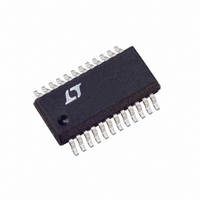
LTC1736IG Linear Technology, LTC1736IG Datasheet - Page 3

LTC1736IG
Manufacturer Part Number
LTC1736IG
Description
IC REG SW SYNC STEPDWN HE 24SSOP
Manufacturer
Linear Technology
Datasheet
1.LTC1736CG.pdf
(28 pages)
Specifications of LTC1736IG
Applications
Converter, Intel Pentium® II, III
Voltage - Input
3.5 ~ 36 V
Number Of Outputs
1
Voltage - Output
0.93 ~ 2 V
Operating Temperature
-40°C ~ 85°C
Mounting Type
Surface Mount
Package / Case
24-SSOP
Lead Free Status / RoHS Status
Contains lead / RoHS non-compliant
Available stocks
Company
Part Number
Manufacturer
Quantity
Price
Part Number:
LTC1736IG
Manufacturer:
LINEAR/凌特
Quantity:
20 000
ELECTRICAL CHARACTERISTICS
temperature range, otherwise specifications are at T
SYMBOL
BG t
BG t
TG/BG T1D
TG/BG T2D
Internal V
V
V
V
V
V
Oscillator
f
f
f
PGOOD Output
V
I
V
VID Control
VIDV
I
R
R
R
V
I
V
Note 1: Absolute Maximum Ratings are those values beyond which the life
of a device may be impaired.
Note 2: T
dissipation P
Note 3: The LTC1736 is tested in a feedback loop that servos V
balance point for the error amplifier (V
Note 4: Dynamic supply current is higher due to the gate charge being
delivered at the switching frequency. See Applications Information.
Note 5: Oscillator frequency is tested by measuring the C
current (I
OSC
H
FCB(SYNC)
PGOOD
VIDVCC
VIDLEAK
INTVCC
LDO(INT)
LDO(EXT)
EXTVCC
EXTVCC(HYS)
PGL
PG
IDT
PULL-UP
VFB/VOSENSE
RATIO
PULL-UP
/f
LTC1736CG, LTC1736IG: T
f
OSC
OSC
r
f
CC
J
OSC
CC
is calculated from the ambient temperature T
C
8 477 10
OSC
) and applying the formula:
Regulator
D
.
according to the following formulas:
( )
pF
PARAMETER
BG Transition Time:
Top Gate Off to Synchronous
Gate-On Delay Time
Synchronous Gate Off to Top
Gate-On Delay Time
Internal V
Internal V
EXTV
EXTV
EXTV
Oscillator Frequency
Maximum Sync Frequency Ratio
FCB Pin Threshold For Sync
PGOOD Voltage Low
PGOOD Leakage Current
PGOOD Trip Level
VID Operating Supply Voltage
VID Supply Current
Resistance Between V
Resistor Ratio Accuracy
VID0 to VID4 Pull-Up Resistance
VID Input Voltage Threshold
VID Input Leakage Current
VID Pull-Up Voltage
(
Rise Time
Fall Time
11
CC
CC
CC
11
)
Drop Voltage
Switchover Voltage
Hysteresis
CC
CC
I
J
CHG
Load Regulation
Voltage
1
= T
A
+ (P
I
DIS
1
ITH
D
OSENSE
• 110 C/W)
–
= 1.2V).
1
and V
FB
A
OSC
and power
A
CONDITIONS
(Note 9)
C
C
C
C
6V < V
I
I
I
(Note 5), C
Ramping Negative
I
V
V
(Note 6) VIDV
Programmed from 0.925V to 2.00V
(Note 7) V
(Note 7) VIDV
VIDV
VIDV
charge
CC
CC
CC
PGOOD
LOAD
LOAD
LOAD
LOAD
PGOOD
OSENSE
= 25 C. V
V
V
FB
OSENSE
OSENSE
= 0mA to 20mA, V
= 20mA, V
= 20mA, EXTV
to the
CC
CC
IN
= 3300pF
= 3300pF
= 3300pF Each Driver
= 3300pF Each Driver
The
= 2mA
= 5V
= 3.3V
= 5V
with Respect to Set Output Voltage
< 30V, V
DIODE
Ramping Negative
Ramping Positive
OSC
IN
CC
CC
EXTVCC
denotes specifications which apply over the full operating
= 43pF
= 15V, V
= 0.6V
= 3.3V
< VID < 7V
EXTVCC
CC
Note 6: With all five VID inputs floating (or tied to VIDV
current is typically < 1 A. However, the VIDV
approximately equal to the number of grounded VID input pins times
(VIDV
detail.)
Note 7: Each built-in pull-up resistor attached to the VID inputs also has a
series diode to allow input voltages higher than the VIDV
damage or clamping. (See the Applications Information section for more
detail.)
Note 8: The minimum on-time condition corresponds to the on inductor
peak-to-peak ripple current 40% of I
considerations in the Applications Information section).
Note 9: Rise and fall times are measured using 10% and 90% levels. Delay
times are measured using 50% levels.
Ramping Positive
= 5V
EXTVCC
= 4V
RUN/SS
CC
– 0.6V)/40k. (See the Applications Information section for more
= 4V
= 5V unless otherwise noted.
– 6.0
MIN
265
5.0
4.5
0.9
2.7
0.4
MAX
6.0
(see minimum on-time
CC
current will rise and be
– 7.5
0.01
0.01
TYP
100
130
300
110
5.2
0.2
4.7
0.2
1.3
1.2
1.0
2.8
4.5
50
40
70
0.05
10
40
7.5
LTC1736
CC
CC
) the VIDV
MAX
– 9.5
200
335
200
5.4
5.5
1.6
90
80
supply without
9.5
1
5
1
1
CC
UNITS
3
kHz
mV
mV
k
k
ns
ns
ns
ns
%
%
%
%
V
V
V
V
A
V
A
V
A
V
V


