DPA424R Power Integrations, DPA424R Datasheet - Page 2
DPA424R
Manufacturer Part Number
DPA424R
Description
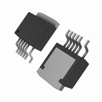
IC CONV DC-DC DPA SWITCH TO263-7
Manufacturer
Power Integrations
Series
DPA-Switch®r
Specifications of DPA424R
Applications
Converter, Power Over Ethernet and Telecom Applications
Voltage - Input
16 ~ 75 V
Number Of Outputs
1
Voltage - Output
220V
Operating Temperature
-40°C ~ 125°C
Mounting Type
Surface Mount
Package / Case
D²Pak, TO-263 (6 leads + tab, variant)
Output Voltage
9 V
Output Current
3.5 A
Input Voltage
- 0.3 V to + 220 V
Switching Frequency
282 KHz to 425 KHz
Operating Temperature Range
- 40 C to + 150 C
Mounting Style
SMD/SMT
Duty Cycle (max)
79 %
For Use With
DAK-21A - KIT DESIGN ACCELERATOR DPA SW
Lead Free Status / RoHS Status
Contains lead / RoHS non-compliant
Available stocks
Company
Part Number
Manufacturer
Quantity
Price
Company:

Part Number:
DPA424R
Manufacturer:
POWER
Quantity:
15 000
Part Number:
DPA424R
Manufacturer:
POWER
Quantity:
20 000
Company:
Part Number:
DPA424R-TL
Manufacturer:
ON
Quantity:
4 300
Company:
Part Number:
DPA424R-TL
Manufacturer:
PI
Quantity:
520
Part Number:
DPA424R-TL
Manufacturer:
POWER
Quantity:
20 000


Functional Block Diagram ....................................................................................................................................... 3
Pin Functional Description ...................................................................................................................................... 3
DPA-Switch Family Functional Description ............................................................................................................ 4
Using Feature Pins ..................................................................................................................................................... 9
Typical Uses of FREQUENCY (F) Pin ...................................................................................................................... 12
Typical Uses of LINE-SENSE (L) and EXTERNAL CURRENT LIMIT (X) Pins ...................................................... 12
Application Examples .............................................................................................................................................. 15
Key Application Considerations ............................................................................................................................. 18
Product Specifications and Test Conditions ......................................................................................................... 22
Typical Performance Characteristics
Part Ordering Information ....................................................................................................................................... 31
Package Outlines .................................................................................................................................................... 32
2
DPA423-426
CONTROL (C) Pin Operation .................................................................................................................................. 4
Oscillator and Switching Frequency ....................................................................................................................... 5
Pulse Width Modulator & Maximum Duty Cycle ..................................................................................................... 6
Minimum Duty Cycle and Cycle Skipping .............................................................................................................. 6
Error Amplifier ......................................................................................................................................................... 6
On-chip Current Limit with External Programmability ............................................................................................. 6
Line Under-Voltage Detection (UV) ......................................................................................................................... 6
Line Overvoltage Shutdown (OV) ........................................................................................................................... 7
Line Feed-Forward with DC
Remote ON/OFF ..................................................................................................................................................... 7
Synchronization ...................................................................................................................................................... 8
Soft-Start ................................................................................................................................................................. 8
Shutdown/Auto-Restart ........................................................................................................................................... 8
Hysteretic Over-Temperature Protection ................................................................................................................. 8
Bandgap Reference ............................................................................................................................................... 8
High-Voltage Bias Current Source .......................................................................................................................... 8
FREQUENCY (F) Pin Operation .............................................................................................................................. 9
LINE-SENSE (L) Pin Operation ............................................................................................................................... 9
EXTERNAL CURRENT LIMIT (X) Pin Operation ...................................................................................................... 9
DPA-Switch Design Considerations ...................................................................................................................... 18
DPA-Switch Layout Considerations ...................................................................................................................... 19
Quick Design Checklist ........................................................................................................................................ 20
Design Tools ......................................................................................................................................................... 20
P
7/05
MAX
Reduction .............................................................................................................. 7
.................................................................................................................. 28
Section List
Related parts for DPA424R
Image
Part Number
Description
Manufacturer
Datasheet
Request
R

Part Number:
Description:
SOP-16
Manufacturer:
Power Integrations
Datasheet:
Part Number:
Description:
DIP8
Manufacturer:
Power Integrations
Datasheet:
Part Number:
Description:
TO-263
Manufacturer:
Power Integrations
Datasheet:
Part Number:
Description:
TO-263
Manufacturer:
Power Integrations
Datasheet:
Part Number:
Description:
Manufacturer:
Power Integrations
Datasheet: