DPA424R Power Integrations, DPA424R Datasheet - Page 4
DPA424R
Manufacturer Part Number
DPA424R
Description
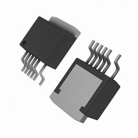
IC CONV DC-DC DPA SWITCH TO263-7
Manufacturer
Power Integrations
Series
DPA-Switch®r
Specifications of DPA424R
Applications
Converter, Power Over Ethernet and Telecom Applications
Voltage - Input
16 ~ 75 V
Number Of Outputs
1
Voltage - Output
220V
Operating Temperature
-40°C ~ 125°C
Mounting Type
Surface Mount
Package / Case
D²Pak, TO-263 (6 leads + tab, variant)
Output Voltage
9 V
Output Current
3.5 A
Input Voltage
- 0.3 V to + 220 V
Switching Frequency
282 KHz to 425 KHz
Operating Temperature Range
- 40 C to + 150 C
Mounting Style
SMD/SMT
Duty Cycle (max)
79 %
For Use With
DAK-21A - KIT DESIGN ACCELERATOR DPA SW
Lead Free Status / RoHS Status
Contains lead / RoHS non-compliant
Available stocks
Company
Part Number
Manufacturer
Quantity
Price
Company:

Part Number:
DPA424R
Manufacturer:
POWER
Quantity:
15 000
Part Number:
DPA424R
Manufacturer:
POWER
Quantity:
20 000
Company:
Part Number:
DPA424R-TL
Manufacturer:
ON
Quantity:
4 300
Company:
Part Number:
DPA424R-TL
Manufacturer:
PI
Quantity:
520
Part Number:
DPA424R-TL
Manufacturer:
POWER
Quantity:
20 000


DPA-Switch Family Functional
Description
DPA-Switch is an integrated switched mode power supply
chip that converts a current at the control input to a duty cycle
at the open drain output of a high voltage power MOSFET.
During normal operation the duty cycle of the power MOSFET
decreases linearly with increasing CONTROL pin current as
shown in Figure 4. A patented high-voltage CMOS technology
allows both the high-voltage power MOSFET and all the low
voltage control circuitry to be cost effectively integrated onto
a single monolithic chip.
In addition to the standard TOPSwitch features, such as the
high-voltage start-up, the cycle-by-cycle current limiting, loop
compensation circuitry, auto-restart and thermal shutdown,
DPA-Switch also offers many advanced features that reduce
system cost and increase power supply performance and design
flexibility. Following is a summary of the advanced features:
1. A fully integrated 5 ms soft-start limits peak currents and
2. A 75% maximum duty cycle (DC
3. High switching frequency (400 kHz/300 kHz, pin selectable)
4. Cycle skipping operation at light load minimizes standby
5. Line under-voltage ensures glitch free operations at both
6. Line overvoltage protects DPA-Switch against excessive
7. External current limit adjustment allows the setting of the
8. Synchronization function allows the synchronization of
9. Remote ON/OFF feature permits DPA-Switch based power
10. Hysteretic over-temperature shutdown provides automatic
11. Tight absolute tolerances and small temperature variations
4
DPA423-426
voltages during start-up and reduces or eliminates output
overshoot in most applications.
line feed-forward with DC
DPA-Switch well suited for both flyback and forward
topologies.
allows the use of smaller size transformers and offers high
bandwidth for power supply control loop.
power consumption (typically <10 mA input current).
power-up and power-down and is tightly toleranced over
process and temperature to meet system level requirements
common in DC to DC converters (e.g. ETSI).
input voltage and line surge.
current limit externally to a lower level near the operating
peak current and, if desired, further adjusts the level
gradually as line voltage rises. This makes possible an ideal
implementation of overload power limiting.
DPA-Switch operation to an external lower frequency.
supplies to be easily switched on/off using logic signals.
Maximum input current consumption is 2 mA in remote
OFF.
recovery from thermal fault.
on switching frequency, current limit, and under-voltage
lock out threshold (UV).
P
7/05
MAX
reduction feature makes
MAX
) together with the
Figure 4. Relationship of Duty Cycle to CONTROL Pin Current.
Three pins, LINE-SENSE (L), EXTERNAL CURRENT LIMIT
(X) and FREQUENCY (F), are used to implement all the pin
controllable features. A resistor from the LINE-SENSE pin to DC
input bus implements line UV, line OV and line feed-forward with
DC
LIMIT pin to the SOURCE pin sets current limit externally. In
addition, remote ON/OFF may be implemented through either
the LINE-SENSE pin or the EXTERNAL CURRENT LIMIT
pin depending on the polarity of the logic signal available as
well as other system specific considerations. Shorting both the
LINE-SENSE and the EXTERNAL CURRENT LIMIT pins to
the SOURCE pin disables line OV, line UV, line feed-forward
with DC
and synchronization. The FREQUENCY pin sets the switching
frequency to 400 kHz if connected to the SOURCE pin, or
300 kHz if connected to the CONTROL pin. This pin should
not be left open. Please refer to “Using Feature Pins” section for
detailed information regarding the proper use of those pins.
CONTROL (C) Pin Operation
The CONTROL pin is a low impedance node that is capable
of receiving a combined supply and feedback current. During
normal operation, a shunt regulator is used to separate the
feedback signal from the supply current. CONTROL pin voltage
V
MOSFET gate driver. An external bypass capacitor closely
connected between the CONTROL and SOURCE pins is required
to supply the instantaneous gate drive current. The total amount
of capacitance connected to this pin also sets the auto-restart
timing as well as control loop compensation.
When the DC input voltage is applied to the DRAIN pin during
start-up, the MOSFET is initially off, and the CONTROL
pin capacitor is charged through the switched high voltage
current source connected internally between the DRAIN and
CONTROL pins. When the CONTROL pin voltage V
C
is the supply voltage for the control circuitry including the
MAX
75
42
4
Auto-restart
reduction. A resistor from the EXTERNAL CURRENT
MAX
reduction, external current limit, remote ON/OFF
I
CD1
I
L
= 115 µA
I
B
I
C
(mA)
Slope = PWM Gain
I
L
< I
L(DC)
PI-2761-112102
C
I
reaches
C (SKIP)
Related parts for DPA424R
Image
Part Number
Description
Manufacturer
Datasheet
Request
R

Part Number:
Description:
SOP-16
Manufacturer:
Power Integrations
Datasheet:
Part Number:
Description:
DIP8
Manufacturer:
Power Integrations
Datasheet:
Part Number:
Description:
TO-263
Manufacturer:
Power Integrations
Datasheet:
Part Number:
Description:
TO-263
Manufacturer:
Power Integrations
Datasheet:
Part Number:
Description:
Manufacturer:
Power Integrations
Datasheet: