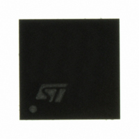
PM6680 STMicroelectronics, PM6680 Datasheet - Page 25

PM6680
Manufacturer Part Number
PM6680
Description
IC CTRLR DUAL STEP DOWN 32VFQFPN
Manufacturer
STMicroelectronics
Datasheet
1.PM6680TR.pdf
(49 pages)
Specifications of PM6680
Applications
Controller, Notebook Power System
Voltage - Input
6 ~ 28 V
Number Of Outputs
2
Voltage - Output
0.9 ~ 5.5 V
Operating Temperature
0°C ~ 85°C
Mounting Type
Surface Mount
Package / Case
32-VFQFN, 32-VFQFPN
Output Voltage
5 V, 0.9 V to 5.5 V, 0.9 V to 3.3 V
Output Current
0.33 A
Input Voltage
5.5 V to 28 V
Mounting Style
SMD/SMT
Maximum Operating Temperature
+ 125 C
Minimum Operating Temperature
- 10 C
For Use With
497-6379 - BOARD EVALUATION FOR PM6680A497-6378 - BOARD EVALUATION FOR PM6680497-6425 - BOARD EVAL BASED ON PM6680A
Lead Free Status / RoHS Status
Lead free / RoHS Compliant
Available stocks
Company
Part Number
Manufacturer
Quantity
Price
Company:
Part Number:
PM6680
Manufacturer:
STMicroelectronics
Quantity:
135
Company:
Part Number:
PM6680
Manufacturer:
INFIONEON
Quantity:
1
Company:
Part Number:
PM6680ATR
Manufacturer:
STMicroelectronics
Quantity:
10 000
Company:
Part Number:
PM6680TR
Manufacturer:
st
Quantity:
1 050
PM6680
7.4
7.5
Pulse skip mode
If the SKIP pin is tied to ground, the device works in skip mode.
At light loads a zero-crossing comparator truncates the low-side switch on-time when the
inductor current becomes negative. In this condition the section works in discontinuous
conduction mode. The threshold between continuous and discontinuous conduction mode
is:
Equation 5
For higher loads the inductor current doesn't cross the zero and the device works in the
same way as in PWM mode and the frequency is fixed to the nominal value.
Figure 31. PWM and pulse skip mode inductor current
Figure 31
average inductor current equal to load current, in SKIP mode some switching cycles are
skipped. When the output ripple reaches the regulated voltage Vreg, a new cycle begins.
The off cycle duration and the switching frequency depend on the load condition.
As a result of the control technique, losses are reduced at light loads, improving the system
efficiency.
No-audible skip mode
If SKIP pin is tied to VREF, a no-audible skip mode with a minimum switching frequency of
33 kHz is enabled. At light load condition, If there is not a new switching cycle within a 30 us
(typ.) period, a no-audible skip mode cycle begins.
0
Ton1 Toff
PWM mode
shows inductor current waveforms in PWM and SKIP mode. In order to keep
Inductor current
ILOAD
(
Ton1=Ton2
SKIP
Load current
)
=
V
IN
2
−
×
V
Ton2
L
OUT
Low side on
Pulse skip mode
×
T
ON
Toff
Low side off
Device description
Time
25/49


