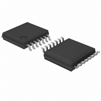
BD9845FV-E2 Rohm Semiconductor, BD9845FV-E2 Datasheet - Page 2

BD9845FV-E2
Manufacturer Part Number
BD9845FV-E2
Description
IC REG SW STEP DOWN 1CH 14-SSOP
Manufacturer
Rohm Semiconductor
Type
Step-Down (Buck)r
Datasheet
1.BD9845FV-E2.pdf
(16 pages)
Specifications of BD9845FV-E2
Internal Switch(s)
No
Synchronous Rectifier
No
Number Of Outputs
1
Current - Output
1A
Frequency - Switching
100kHz ~ 1.5MHz
Voltage - Input
3.6 ~ 35 V
Operating Temperature
-40°C ~ 85°C
Mounting Type
Surface Mount
Package / Case
14-SSOP
Power - Output
500mW
Lead Free Status / RoHS Status
Lead free / RoHS Compliant
Voltage - Output
-
Lead Free Status / Rohs Status
Lead free / RoHS Compliant
Other names
BD9845FV-E2TR
●Electric characteristics (Ta=25C, VCC=6V unless otherwise specified)
© 2009 ROHM Co., Ltd. All rights reserved.
BD9845FV
www.rohm.com
[VREF output unit]
[Triangular wave oscillator]
[Soft start unit]
[Pause period adjusting circuit]
[Low input malfunction preventing circuit]
[Error amplifier]
[PWM comparator]
[Output unit]
[Overcurrent protection circuit]
[Standby changeover unit]
[Device overall]
Output voltage
Input stability
Load stability
Current capacity
Oscillation frequency
Frequency fluctuation
SS source current
SS sink current
DT input bias current
DT sink current
Threshold voltage
Hysteresis
Non-inverting input reference voltage
Reference voltage supply fluctuation
INV input bias current
Open gain
Max output voltage
Min output voltage
Output sink current
Output source current
Input threshold voltage(fosc=100kHz)
Output ON resistance H
Output ON resistance L
C5V clamp voltage
Overcurrent detection threshold voltage
OCP-input bias current
Overcurrent detection delay time
Overcurrent detection minimum
retention time
STB flow-in current
Standby mode setting range
Active (master) mode setting range
SEL flow-in current
Master
Slave mode setting range
Standby current
Average power consumption
* Radiation resistance design is not applied.
mode setting range
Item
Load reg.
Line reg.
Symbol
V
tdocpre
tdocpth
V
V
V
V
I
V
V
I
dVinv
I
R
F
V
R
I
V
V
Vt
OMAX
I
I
V
V
I
OCPTH
SSSO
I
I
FBSO
OCP
I
I
F
SSSI
DTSI
UHYS
FBSI
CLMP
Vt
STBH
SELH
CCS
CCA
I
AV
STB
STBL
SEL
SELL
OSC
UTH
I
ONH
REF
FBH
ONL
DT
FBL
INV
DV
IB
100
0
-
2.450
0.99
2.30
0.04
Min.
1.4
3.0
0.5
1.4
1.9
4.5
0.8
3.0
2.0
95
65
50
-
-
-
-
-
-
-
-
-
-
-
-
-
2
5
1
0
0
1
-
-
Standard value
2/15
2.500
Typ.
0.15
0.05
106
105
200
0.1
3.3
3.2
0.6
1.5
1.5
4.0
3.3
0.1
1.6
2.4
13
12
85
55
15
-
1
2
0
2
1
1
0
2
5
0
-
-
-
-
VREF
2.550
Max.
0.25
1.01
0.06
V
V
117
400
100
2.6
3.4
1.3
1.6
2.1
5.5
0.5
0.5
10
10
10
10
10
30
-
-
-
-
-
-
-
1
1
6
1
1
4
CC
CC
Unit
kHz
mV
mV
mA
mA
mA
mV
mA
mA
ms
µA
µA
µA
dB
µA
µA
µA
µA
µA
ns
%
Ω
Ω
V
V
V
V
V
V
V
V
V
V
V
V
V
V
Vcc start detection
INV=FB
Vcc=3.6 V→35 V
INV=1 V
FB=1.25 V, INV=1.5 V
FB=1.25 V, INV=0.5 V
On duty 0%
On duty 100%
R
R
V
Voltage between(OCP+) and (OCP-)
OCP+= V
OCP-= V
OCP-= V
STB=6V
SEL=2.5V
STB=0 V
INV=0 V, FB=H, DT=1.75 V
I
Vcc=3.6 V→35 V
I
V
C
Vcc=3.6 V→35 V
SS=0.5 V
SS=0.5 V
DT=1.75 V
DT=1.75 V, (OCP+)-(OCP-)=0.5 V
O
O
CLMP
REF
ONH
ONL
CP
=0.1 mA
=0.1 mA→2 mA
=1800 pF
=(typ.)×0.95
=(OUT-C5 V)/ Iout, Iout=0.1 A
=(V
= V
CC
CC
CC
CC,
CC
→V
-0.2 V→V
-OUT)/ Iout, Iout=0.1 A
-C5V , V
OCP-= V
Condition
CC
2009.05 - Rev.A
Technical Note
-0.2 V
CC
CC
CC
>7 V
-0.5 V


