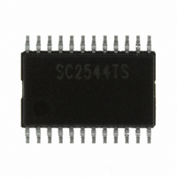
SC2544TSTRT Semtech, SC2544TSTRT Datasheet - Page 16

SC2544TSTRT
Manufacturer Part Number
SC2544TSTRT
Description
IC CTRL/REG SYNC BUCK 24-TSSOP
Manufacturer
Semtech
Type
Step-Down (Buck)r
Datasheet
1.SC2544TSTRT.pdf
(24 pages)
Specifications of SC2544TSTRT
Internal Switch(s)
No
Synchronous Rectifier
No
Number Of Outputs
2
Voltage - Output
Adj to 0.75V
Frequency - Switching
100kHz ~ 300kHz
Voltage - Input
4.5 ~ 28 V
Operating Temperature
-40°C ~ 85°C
Mounting Type
Surface Mount
Package / Case
24-TSSOP
Lead Free Status / RoHS Status
Lead free / RoHS Compliant
Current - Output
-
Power - Output
-
Other names
SC2544TSTR
The compensator in Figure 10 includes an error am-
plifier and impedance networks Zf and Zs. It is imple-
mented by the circuit in Figure 12. The compensator
provides an integrator, double poles, and double ze-
ros.
boost the gain at low frequency. Two zeros are intro-
duced to compensate excessive phase lag at the
loop gain crossover due to the integrator (-90deg)
and the complex pole pair (-180deg). Two high fre-
quency poles are designed to compensate the ESR
zero and to attenuate high frequency noise.
POWER MANAGEMENT
Applications Information (Cont.)
2005 Semtech Corp.
Vc
As shown in Figure 11, the integrator is used to
Fig. 11. Bode plots for control loop design.
Fig. 12. Compensation network.
F z1
F z1
E/A
C1
Out
F o
F o
C2
F z2
F z2
+
-
R2
F R E Q U E N C Y (H z)
F R E Q U E N C Y (H z)
F p 1
F p 1
F z
F z
0.75V
C O M P E N S A T O R G A I N
C O M P E N S A T O R G A I N
Rbot
C3
Rtop
F c
F c
R3
F p 2
F p 2
Vo
16
A resistive divider is used to program the output volt-
age. The top resistor R
can be chosen from 20k
tom resistor R
(2). Select the open loop crossover frequency Fc lo-
cated at 10% to 20% of the switching frequency. At
Fc, find the required DC gain.
(3). Use the first compensator pole Fp1 to cancel the
ESR zero Fz.
(4). Have the second compensator pole Fp2 at half
the switching frequency to attenuate the switching
ripple and high frequency noise.
(5). Place the first compensator zero Fz1 at or below
50% of the power stage resonant frequency Fo.
(6). Place the second compensator zero Fz2 at or
below the power stage resonant frequency Fo.
A MathCAD program is available upon request for the
calculation of the compensation parameters.
where 0.75V is the internal reference voltage of the
SC2544.
The other components of the compensator can be
calculated using following design procedure:
(1). Plot the converter gain, including LC filter and
PWM modulator.
Rbot
bot
is found from:
Vo
. 0
top
75
. 0
V
75
to 30k
of the divider in Fig. 12
V
Rtop
www.semtech.com
. Then the bot-
SC2544


