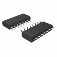
MIC2182-5.0YM Micrel Inc, MIC2182-5.0YM Datasheet - Page 12

MIC2182-5.0YM
Manufacturer Part Number
MIC2182-5.0YM
Description
IC CTRLR SYNC BUCK 5.0V 16-SOIC
Manufacturer
Micrel Inc
Type
Step-Down (Buck)r
Datasheet
1.MIC2182-5.0YSM.pdf
(28 pages)
Specifications of MIC2182-5.0YM
Internal Switch(s)
No
Synchronous Rectifier
Yes
Number Of Outputs
1
Voltage - Output
5V
Current - Output
20A
Frequency - Switching
300kHz
Voltage - Input
4.5 ~ 16.5 V
Operating Temperature
-40°C ~ 85°C
Mounting Type
Surface Mount
Package / Case
16-SOIC (3.9mm Width)
Power - Output
400mW
Lead Free Status / RoHS Status
Lead free / RoHS Compliant
Other names
576-2158
MIC2182-5.0YM
MIC2182-5.0YM
Available stocks
Company
Part Number
Manufacturer
Quantity
Price
Company:
Part Number:
MIC2182-5.0YM
Manufacturer:
MICREL
Quantity:
48
Company:
Part Number:
MIC2182-5.0YM
Manufacturer:
MICREL
Quantity:
784
Part Number:
MIC2182-5.0YM
Manufacturer:
MICREL/麦瑞
Quantity:
20 000
MIC2182
A hysteretic comparator is used in place of the PWM error
amplifier and a current-limit comparator senses the inductor
current. A one-shot starts the switching cycle by momentarily
turning on the low side MOSFET to insure the high-side drive
boost capacitor, Cbst, is fully charged. The high-side MOS-
FET is turned on and current ramps up in the inductor, L1.
The high-side drive is turned off when either the peak voltage
on the input of the current-sense comparator exceeds the
threshold, typically 35mV, or the output voltage rises above
the hysteretic threshold of the output voltage comparator.
Once the high-side MOSFET is turned off, the load current
discharges the output capacitor, causing V
cycle repeats when V
1%.
The maximum peak inductor current depends on the skip-
mode current-limit threshold and the value of the current-
sense resistor, R
M9999-042204
I
inductor(peak)
CS
.
R
35mV
OUT
sense
falls below the lower threshold, –
V
one-shot
Reset
Pulse
V
V
V
V
V
V
V
I
HSD
HSD
OUT
OUT
LSD
LSD
SW
I
SW
I
L1
L1
V
V
IN
I
NOMINAL
LIM(skip)
+ V
I
LOAD
V
V
V
V
V
V
OUT
+1%
V
V
–1%
0A
0V
0V
0V
0V
0A
0V
0V
0A
0V
DD
DD
0V
DD
DD
DD
0V
DD
IN
IN
OUT
Figure 5a. PWM-Mode Timing
Figure 5b. Skip-Mode Timing
to fall. The
12
Figure 6 shows the improvement in efficiency that skip mode
makes when at lower output currents.
100
80
60
40
20
0.01
Figure 6. Efficiency
0
Skip
OUTPUT CURRENT (A)
0.1
1
10
PWM
100
April 22, 2004
Micrel


