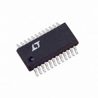
LTC3713EG Linear Technology, LTC3713EG Datasheet - Page 18

LTC3713EG
Manufacturer Part Number
LTC3713EG
Description
IC DC/DC CONTROLLER SYNC 24-SSOP
Manufacturer
Linear Technology
Type
Step-Down (Buck)r
Datasheet
1.LTC3713EGPBF.pdf
(24 pages)
Specifications of LTC3713EG
Internal Switch(s)
No
Synchronous Rectifier
Yes
Number Of Outputs
1
Voltage - Output
0.8 ~ 32.4 V
Current - Output
2A
Voltage - Input
1.5 ~ 36 V
Operating Temperature
-40°C ~ 85°C
Mounting Type
Surface Mount
Package / Case
24-SSOP
Lead Free Status / RoHS Status
Contains lead / RoHS non-compliant
Power - Output
-
Frequency - Switching
-
Available stocks
Company
Part Number
Manufacturer
Quantity
Price
Company:
Part Number:
LTC3713EG
Manufacturer:
LINEAR
Quantity:
208
Part Number:
LTC3713EG
Manufacturer:
LINEAR/凌特
Quantity:
20 000
Part Number:
LTC3713EG#PBF
Manufacturer:
LINEAR/凌特
Quantity:
20 000
Part Number:
LTC3713EG#TRPBF
Manufacturer:
LINEAR/凌特
Quantity:
20 000
APPLICATIO S I FOR ATIO
LTC3713
C
temperature. The output capacitors are chosen for a low
ESR of 0.005 to minimize output voltage changes due to
inductor ripple current and load steps. The ripple voltage
will be only:
PGOOD
18
IN
T
P
J
is chosen for an RMS current rating of about 6A at
V
5.6k
R
R
10k
TOP
= 50 C + (0.68W)(50 C/W) = 84 C
OUT(RIPPLE)
F2
F1
0 68
1 25
1 7 3 3
3 3
.
.
.
.
R
100k
V
W
V
PG
= I
= (2.6A) (0.005 ) = 13mV
680pF
.
10 2
R
10k
C1
U
R1
V
.
L(MAX)
12.1k
237k
A
R
10 2
20k
R
39.2k
R
R
ON
F3
C
R2
U
2
.
1 3 0 013
A
(ESR)
.
C2
100pF
Figure 7. Design Example: 1.25V/6A at 300kHz from 1.8V to 3.3V
2
10k
R
0.1 F
F5
C
60
SS
.
10
11
12
W
pF
1
2
3
4
5
6
7
8
9
RUN/SS
V
PGOOD
V
FCB
I
SGND1
I
V
SHDN
SGND2
V
TH
ON
ON
RNG
FB1
FB2
300
LTC3713
1000pF
37.4k
C
R
kHz
F4
F4
SENSE
SENSE
PGND1
INTV
PGND2
BOOST
U
SW1
SW2
V
V
IN1
IN2
TG
BG
CC
+
–
24
23
22
21
20
19
18
17
16
15
14
13
MBR0520
C
4.7 F
IN2
D3
However, a 0A to 6A load step will cause an output change
of up to:
The inductor for the boost converter is selected by first
choosing an allowable ripple current. The boost converter
will be operating in discontinous mode. If we select a ripple
current of 170mA for the boost converter, then:
The complete circuit is shown in Figure 7.
D
CMDSH-3
C
0.33 F
C
10 F
6V
X5R
B
VCC
B
L
V
OUT(STEP)
(
170
3 3 1
.
L2
4.7 H
V
mA
M1
IRF7811A
M2
IRF7811A
)( .
= I
C
C
C
C
L1: TOKO D104C-1 H
L2: PANASONIC ELJPC4R7MF
IN
IN2
VCC
OUT
1 4
: TAIYO YUDEN JMK325BJ226MM
3 3
: TAIYO YUDEN JMK212BJ475M6
: TAIYO YUDEN JMK316BJ106ML
: PANASONIC EEFUEDD271R
5
1 H
.
LOAD
L1
MHz
V
V
D2
B340A
(ESR) = (6A) (0.005 ) = 30mV
)
+
4 7
.
C
270 F
OUT
2
H
3713 F07
C
22 F
IN
2
V
1.8V TO 3.3V
V
1.25V
6A
IN
OUT
3713fa


