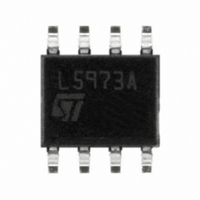
L5973AD STMicroelectronics, L5973AD Datasheet - Page 9

L5973AD
Manufacturer Part Number
L5973AD
Description
IC REG SW 2A STEPDOWN 8-SOIC
Manufacturer
STMicroelectronics
Type
Step-Down (Buck)r
Datasheet
1.L5973ADTR.pdf
(22 pages)
Specifications of L5973AD
Internal Switch(s)
Yes
Synchronous Rectifier
No
Number Of Outputs
1
Voltage - Output
1.24 ~ 35 V
Current - Output
2A
Frequency - Switching
500kHz
Voltage - Input
4 ~ 36 V
Operating Temperature
-40°C ~ 150°C
Mounting Type
Surface Mount
Package / Case
8-SOIC (3.9mm Width) Exposed Pad, 8-eSOIC. 8-HSOIC
Power - Output
2.25W
Output Voltage
35 V
Output Current
2 A
Input Voltage
4 V to 36 V
Switching Frequency
500 KHz
Operating Temperature Range
- 40 C to + 150 C
Mounting Style
SMD/SMT
Duty Cycle (max)
100 %
Low Dropout Operation
100 % duty cycle
For Use With
497-4134 - EVAL BOARD FOR L5973 SERIES497-4133 - EVAL BOARD FOR L5973 SERIES
Lead Free Status / RoHS Status
Lead free / RoHS Compliant
Other names
497-1417-5
497-1417-5
497-4565-5
E-L5973AD
497-1417-5
497-4565-5
E-L5973AD
Available stocks
Company
Part Number
Manufacturer
Quantity
Price
Part Number:
L5973AD
Manufacturer:
ST
Quantity:
20 000
Part Number:
L5973AD013TR
Manufacturer:
ST
Quantity:
20 000
Company:
Part Number:
L5973ADTR
Manufacturer:
st
Quantity:
4 114
Company:
Part Number:
L5973ADTR
Manufacturer:
STM
Quantity:
9 180
Company:
Part Number:
L5973ADTR-LF5
Manufacturer:
STM
Quantity:
1 552
L5973AD
4.4
In particular, connecting together two devices, the one with the lower switching frequency
works as Slave and the other one works as Master.
To synchronize the device, the SYNC pin has to pass from a low level to a level higher than
the synchronization threshold with a duty cycle that can vary approximately from 10% to
90%, depending also on the signal frequency and amplitude.
The frequency of the synchronization signal must be at least higher than the internal
switching frequency of the device (500 kHz).
Figure 5.
Current protection
The L5973AD has two current limit protections, pulse by pulse and frequency fold back.
The schematic of the current limitation circuitry for the pulse by pulse protection is shown in
Figure
The output power PDMOS transistor is split in two parallel PDMOS. The smallest one has a
resistor in series, R
threshold, the mirror is unbalanced and the PDMOS is switched off until the next falling edge
of the internal clock pulse.
Due to this reduction of the ON time, the output voltage decreases.
Since the minimum switch ON time (necessary to avoid false overcurrent signal) is not
enough to obtain a sufficiently low duty cycle at 500 kHz, the output current, in strong
overcurrent or short circuit conditions, could increase again. For this reason the switching
frequency is also reduced, so keeping the inductor current under its maximum threshold.
The Frequency Shifter (see
voltage decreases (due to the reduced duty cycle), the switching frequency decreases too.
6.
Ibias_osc
Oscillator circuit
FREQUENCY
GENERATOR
D00IN1131
SHIFTER
CLOCK
SENSE
. The current is sensed through Rsense and if reaches the
Figure
Doc ID 9552 Rev 9
5) depends on the feedback voltage. As the feedback
SYNCHRONIZATOR
GENERATOR
RAMP
CLOCK
RAMP
SYNC
Functional description
t
9/22


