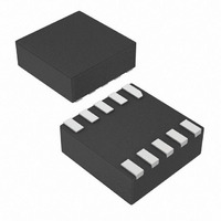
MAX4959ELB+T Maxim Integrated Products, MAX4959ELB+T Datasheet

MAX4959ELB+T
Specifications of MAX4959ELB+T
MAX4959ELB+TTR
Related parts for MAX4959ELB+T
MAX4959ELB+T Summary of contents
Page 1
... MAX4959 MAX4960 + MAX4960 ONLY. ________________________________________________________________ Maxim Integrated Products For pricing delivery, and ordering information please contact Maxim Direct at 1-888-629-4642, or visit Maxim’s website at www.maxim-ic.com. o Overvoltage Protection Up to +28V o ± 2.5% Accurate Externally Adjustable OVLO/UVLO Thresholds o Battery Switchover pFET Control o Protection Against Incorrect Power Adapter o Low (100µ ...
Page 2
High-Voltage OVP with Battery Switchover ABSOLUTE MAXIMUM RATINGS IN, SOURCE1, GATE1, GATE2, to GND ................-0.3V to +30V V to GND ..............................................................-0.3V to +6V DD UVS, OVS GND .............................................-0.3V to +6V Continuous Power Dissipation (T = +70°C) A 10-pin ...
Page 3
High-Voltage OVP with Battery Switchover ELECTRICAL CHARACTERISTICS (continued +19V -40°C to +85°C, unless otherwise noted PARAMETER SYMBOL GATE1 Leakage Current G1I GATE2 Leakage Current G2I CB Logic-Level High Logic-Level Low CB Pulldown Resistor ...
Page 4
High-Voltage OVP with Battery Switchover (V = 22.2V and V = 10.1V 887kΩ 66.5kΩ 54.9kΩ, all resistors 1%, OV OVLO UVLO LOW-POWER ADAPTER RESPONSE (V = 22.3V 10.1V, pFET = IRF7726) OVLO ...
Page 5
High-Voltage OVP with Battery Switchover PIN NAME MAX4959 MAX4960 1 1 GATE1 N.C. — 2 SOURCE1 UVS 5 5 OVS GND 10 10 ...
Page 6
High-Voltage OVP with Battery Switchover VREF2 = 0.7V VREF1 = 2V OVS UVS MAX4959 no blanking time for OVP, but the debounce time applies once the IN voltage falls below V above V . When the ...
Page 7
High-Voltage OVP with Battery Switchover VREF2 = 0.7V VREF1 = 2V OVS UVS MAX4960 only if the backup capacitor maintain power for greater than the 10ms blanking time. The detection that the adapter ...
Page 8
High-Voltage OVP with Battery Switchover OVLO t DEB V GATE1 GATE2 Figure 1. Timing Diagram The following table lists the different modes of operations: IN RANGE V > OFF (not ...
Page 9
High-Voltage OVP with Battery Switchover Applications Information MOSFET Configuration and Selection The MAX4959/MAX4960 are used with a single MOS- FET configuration as shown in the Typical Operating Circuits to regulate voltage as a low-cost solution. The MAX4959/MAX4960 are designed with ...
Page 10
High-Voltage OVP with Battery Switchover 1.5k 1M DISCHARGE CHARGE-CURRENT- RESISTANCE LIMIT RESISTOR HIGH STORAGE VOLTAGE 100pF CAPACITOR DC SOURCE Figure 2. Human Body ESD Test Model Chip Information PROCESS: BiCMOS 10 ______________________________________________________________________________________ I 100% ...
Page 11
High-Voltage OVP with Battery Switchover AC ADAPTER IN HOLD-UP POWER SUPPLY UVS R2 OVS R3 Figure 4. MAX4959 Typical Operating Circuit 1 ______________________________________________________________________________________ RU1 RD1 GATE1 V SUPPLY N1 V REF UVLO LOGIC OVLO ...
Page 12
High-Voltage OVP with Battery Switchover AC ADAPTER UVS R2 OVS R3 Figure 5. MAX4959 Typical Operating Circuit 2 12 ______________________________________________________________________________________ Typical Operating Circuits (continued) 28V PROTECTED CHARGER EN 3.3V RD1 GATE1 V SUPPLY HOLD-UP N1 POWER ...
Page 13
High-Voltage OVP with Battery Switchover AC ADAPTER IN HOLD-UP POWER SUPPLY UVS R2 OVS R3 Figure 6. MAX4960 Typical Operating Circuit 1 ______________________________________________________________________________________ Typical Operating Circuits (continued SOURCE1 GATE1 V SUPPLY N1 V REF UVLO ...
Page 14
High-Voltage OVP with Battery Switchover AC ADAPTER UVS R2 OVS R3 Figure 7. MAX4960 Typical Operating Circuit 2 14 ______________________________________________________________________________________ Typical Operating Circuits (continued SOURCE1 GATE1 V SUPPLY HOLD-UP N1 POWER SUPPLY V REF ...
Page 15
High-Voltage OVP with Battery Switchover (The package drawing(s) in this data sheet may not reflect the most current specifications. For the latest package outline information www.maxim-ic.com/packages.) D XXXX XXXX XXXX SAMPLE PIN 1 INDEX AREA MARKING 7 A1 ...
Page 16
High-Voltage OVP with Battery Switchover (The package drawing(s) in this data sheet may not reflect the most current specifications. For the latest package outline information www.maxim-ic.com/packages.) COMMON DIMENSIONS SYMBOL MIN. NOM. A 0.70 0.75 A1 0.15 0.20 A2 ...
Page 17
... Maxim cannot assume responsibility for use of any circuitry other than circuitry entirely embodied in a Maxim product. No circuit patent licenses are implied. Maxim reserves the right to change the circuitry and specifications without notice at any time. Maxim Integrated Products, 120 San Gabriel Drive, Sunnyvale, CA 94086 408-737-7600 ____________________ 17 © 2007 Maxim Integrated Products ...


