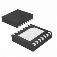
MAX4920BETD+T Maxim Integrated Products, MAX4920BETD+T Datasheet - Page 12

MAX4920BETD+T
Manufacturer Part Number
MAX4920BETD+T
Description
IC CTLR OVP/OCP BATT PWR 14-TDFN
Manufacturer
Maxim Integrated Products
Datasheet
1.MAX4921BETDT.pdf
(19 pages)
Specifications of MAX4920BETD+T
Applications
*
Mounting Type
Surface Mount
Package / Case
14-TDFN Exposed Pad
Lead Free Status / RoHS Status
Lead free / RoHS Compliant
The MAX4919B/MAX4920B/MAX4921B are designed
for use with a complementary MOSFET or single
p-channel and dual back-to-back n-channel MOSFETS.
In most situations, MOSFETs with R
a V
30V in order for the MOSFET to withstand the full 28V IN
range of the MAX4919B/MAX4920B/MAX4921B. Table
1 shows a selection of MOSFETs which are appropriate
for use.
For most applications, bypass IN to GND with a 1µF
ceramic capacitor to enable ±15kV ESD protection
(when GP1 is not utilized). If ±15kV is not required,
place a minimum 0.1µF capacitor at IN to GND. If the
power source has significant inductance due to long
lead length, take care to prevent overshoots due to the
LC tank circuit and provide protection if necessary to
prevent exceeding the +30V absolute maximum rating
at IN.
Battery Power-Up Logic with Overvoltage
and Overcurrent Protection
Table 1. MOSFET Suggestions
12
Si5504DC
Si5902DC
Si1426DH
Si5435DC
FDC6561AN
FDG315N
FDC658P
FDC654P
GS
______________________________________________________________________________________
PART
of 4.5V will work well. Also, the V
IN Bypass Considerations
CONFIGURATION/
MOSFET/1206-8
Complementary
Single/µDFN-6
Single/µDFN-6
Single/SSOT-6
Single/SSOT-6
Single/1206-8
Dual/SSOT-6
Dual/1206-8
PACKAGE
MOSFET Selection
DS(ON)
DS
specified for
should be
V
GS
±20
±20
±20
±20
±20
±20
±20
±20
(V)
(MAX)
In order to guarantee a successful startup of the inter-
nal p-channel MOSFET, use a capacitance lower than
C
current may not have enough time to charge the
capacitance and the device assumes that there is a
faulty load condition. The maximum capacitive-load
value that can be driven by BTO is obtained by the fol-
lowing formula:
where C
the battery voltage, t
blanking time, and I
rent-limit value.
V
BTO(MAX)
DS
-30
-30
-30
-30
(V)
30
30
30
30
30
(MAX)
BTO Bypass Capacitor Considerations
BTO
. If the load capacitance is too large, then
is the output capacitor at BTO, V
C
BTO MAX
R
ON
(N-FET)
(N-FET)
(N-FET)
(N-FET)
(N-FET)
(P-FET)
(P-FET)
(P-FET)
(P-FET)
(mΩ)
(
143
290
143
115
145
160
125
80
75
at 4.5V
CLIM
CLIM
)
≤
is the minimum forward cur-
is the minimum current-limit
I
LIM
Vishay Siliconix
www.vishay.com
Fairchild Semiconductor
www.fairchildsemi.com
V
×
BTI
t
CLIM
MANUFACTURER
BTI
is


