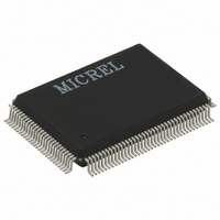
KS8842-32MQL Micrel Inc, KS8842-32MQL Datasheet - Page 37

KS8842-32MQL
Manufacturer Part Number
KS8842-32MQL
Description
IC SWITCH 10/100 32BIT 128PQFP
Manufacturer
Micrel Inc
Specifications of KS8842-32MQL
Applications
*
Mounting Type
Surface Mount
Package / Case
128-MQFP, 128-PQFP
Number Of Primary Switch Ports
2
Internal Memory Buffer Size
32
Operating Supply Voltage (typ)
3.3V
Fiber Support
Yes
Integrated Led Drivers
Yes
Phy/transceiver Interface
MII
Power Supply Type
Analog/Digital
Package Type
PQFP
Data Rate (typ)
10/100Mbps
Vlan Support
Yes
Operating Temperature (max)
70C
Operating Temperature (min)
0C
Pin Count
128
Mounting
Surface Mount
Jtag Support
No
Operating Supply Voltage (max)
3.5V
Operating Supply Voltage (min)
3.1V
Operating Temperature Classification
Commercial
Data Rate
100Mbps
Lead Free Status / RoHS Status
Lead free / RoHS Compliant
For Use With
KS8842-PMQL-EVAL - EVAL KIT EXPERIMENTAL KS8842KS8842-16MQL-EVAL - EVAL KIT EXPERIMENTAL KS8842
Lead Free Status / RoHS Status
Not Compliant, Lead free / RoHS Compliant
Other names
576-1459
Available stocks
Company
Part Number
Manufacturer
Quantity
Price
physical data bus. For example, for a 32-bit system/host data bus, it allows 8, 16, and 32-bit data transfers (KSZ8842-
32MQL); for a 16-bit system/host data bus, it allows 8 and 16-bit data transfers (KSZ8842-16MQL); and for 8-bit
system/host data bus, it only allows 8-bit data transfers (KSZ8842-16MQL).
Note that KSZ8842M does not support internal data byte-swap but it does support internal data word-swap. This means
that the system/host data bus HD[7:0] has to connect to both D[7:0] and D[15:8] for 8-bit data bus interfaces. However,
the system/host data bus HD[15:8] and HD[7:0] just connects to D[15:8] and D[7:0], respectively, for 16-bit data bus
interface; there is no need to connect HD[31:24] and HD[23:16] to D[31:24] and D[23:16].
Table 2 describes the BIU signal grouping.
Micrel, Inc.
October 2007
Signal
Common Signals
A[15:1]
AEN
BE3N, BE2N,
BE1N, BE0N
D[31:16]
D[15:0]
ADSN
LDEVN
DATACSN
INTRN
Synchronous Transfer Signals
VLBUSN
Type
I
I
I
I/O
I/O
I
O
I
O
I
(1)
Function
Address
Address Enable
Address Enable asserted indicates memory address on the bus for DMA
access and since the device is an I/O device, address decoding is only enabled
when AEN is low.
Byte Enable
Note 1: BE3N, BE2N, BE1N and BE0N are ignored when DATACSN is low
because 32 bit transfers are assumed.
Note 2: BE2N and BE3N are valid only for the KSZ8842-32 mode, and are NC
for the KSZ8842-16 mode.
Data
For KSZ8842-32 Mode only
Data
For both KSZ8842-32 and KSZ8842-16 Modes
Address Strobe
The rising edge of ADSN is used to latch A[15:1], AEN, BE3N, BE2N, BE1N
and BE0N.
Local Device
This signal is a combinatorial decode of AEN and A[15:4], The A[15:4] is used
to compare against the Base Address Register.
Data Register Chip Select (For KSZ8842-32 Mode only)
This signal is used for central decoding architecture (mostly for embedded
application). When asserted, the device’s local decoding logic is ignored and
the 32-bit access to QMU Data Register is assumed.
Interrupt
VLBUSN = 0, VLBus-like cycle.
VLBUSN = 1, burst cycle (both host/system and KSZ8842 can insert wait state)
BE0N
0
0
1
0
1
1
1
BE1N
0
0
1
1
0
1
1
37
BE2N
0
1
0
1
1
0
1
BE3N
0
1
0
1
1
1
0
Description
32-bit access (32-bit bus only)
Lower 16-bit (D[15:0]) access
Higher 16-bit (D[31:16]) access
(32-bit bus only)
Byte 0 (D[7:0]) access
Byte 1 (D[15:8]) access
Byte 2 (D[23:16]) access (32-bit
bus only)
Byte 3 (D[31:24]) access (32-bit
bus only)
KSZ8842-16/32 MQL/MVL/MVLI/MBL
M9999-102207-1.9


