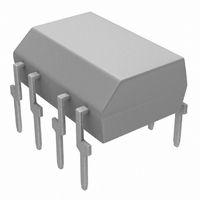
TLP2601 Toshiba, TLP2601 Datasheet

TLP2601
Specifications of TLP2601
Available stocks
Related parts for TLP2601
TLP2601 Summary of contents
Page 1
... Microprocessor System Interface Digital Isolation For A/D, D/A Conversion Direct Replacement For HCPL−2601 The TOSHIBA TLP2601 a photocoupler which combines a GaAℓAs IRed as the emitter and an integrated high gain, high speed photodetector. The output of the detector circuit is an open collector, Schottky clamped transistor ...
Page 2
... I 6.3 (*) 20 FH ⎯ V 4.5 5.5 CC ⎯ ⎯ 0.8 EL ⎯ ⎯ N ⎯ opr (no derating required) Symbol Rating −0.5 5 −40~85 T opr −55~125 T stg (**) T 260 sol 2500 BV S (Note 10) 3540 2 TLP2601 Unit μ ⎯ 8 °C Unit °C °C °C Vrms V dc 2007-10-01 ...
Page 3
... A F Relative humidity = 45% I Ta=25℃ second I− 3000Vdc, (Note 10) I− 500V, R.H.≤ 60% I−O R I−O (Note 10 1MHz, (Note 10) I− 25°C. 3 TLP2601 Min. Typ. Max. Unit ⎯ μA 1 250 ⎯ 0.4 0.6 V ⎯ ⎯ ⎯ −1.6 − ...
Page 4
... EHL (Note 6)&(Note 400V 350Ω O(min 0mA 400V 350Ω 0.8V O(max 7.5mA TLP2601 Min. Typ. Max. ― 15pF ― ― 30 ― ― 30 ― = 15pF ― 25 ― ― 25 ― 1000 10000 ― (Note 9) −1000 −10000 ― (Note 8) 2007-10-01 Unit ...
Page 5
... V O Switch 0mA Switch 5mA F Pulse generator I = 7.5mA 50Ω 3.75mA 5ns Monitoring node 1. Pulse generator = 50 Ω 5ns r 3.0V 7.5mA 1. 1. 400V TLP2601 (*) GND Input V E monitoring node (*) GND GND Pulse gen Ω 2007-10- Output monitor- ing node Output monitor- ing ...
Page 6
... Forward current I (mA) F -2.6 -2.4 -2.2 -2.0 -1.8 -1.6 -1.4 0.1 0.3 1.8 100 0 =350Ω =4kΩ 0 TLP2601 ΔV / ΔTa – Forward current I (mA – 250μ 5. 5. Ambient temperature Ta (°C) V – 5mA 5. =16mA 12.8mA 9.6mA 6.4mA Ambient temperature Ta (°C) ...
Page 7
... Ambient temperature Ta (° 4kΩ 7.5mA 60 1kΩ 350Ω 30 350Ω 1kΩ 20 4kΩ Ambient temperature Ta (°C) 7 TLP2601 t t – Ta pHL, pLH 4kΩ t pLH 350Ω 1kΩ t pLH 350Ω 1kΩ t pHL 4kΩ 7.5mA – Ta EHL, ELH 4kΩ t ELH 1kΩ t ELH 350Ω ...
Page 8
... Notes 1. The V supply voltage to each TLP2601 isolator must be bypassed by a 0.1μF capacitor of larger.This can be CC either a ceramic or solid tantalum capacitor with good high frequency characteristic and should be connected as close as possible to the package Propagation delay is measured from the 3.75mA level on the low to high transition of the input ・ ...
Page 9
... Please contact your TOSHIBA sales representative for details as to environmental matters such as the RoHS compatibility of Product. Please use Product in compliance with all applicable laws and regulations that regulate the inclusion or use of controlled substances, including without limitation, the EU RoHS Directive. TOSHIBA assumes no liability for damages or losses occurring as a result of noncompliance with applicable laws and regulations. 9 TLP2601 2007-10-01 ...


