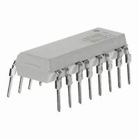
TCET4100 Vishay, TCET4100 Datasheet - Page 5

TCET4100
Manufacturer Part Number
TCET4100
Description
OPTOCP PHOTOTRANS 4CH 600% 16DIP
Manufacturer
Vishay
Datasheet
1.TCET4100.pdf
(9 pages)
Specifications of TCET4100
Mounting Type
Through Hole
Isolation Voltage
5000 Vrms
Number Of Channels
4
Input Type
DC
Voltage - Isolation
5000Vrms
Current Transfer Ratio (min)
50% @ 5mA
Current Transfer Ratio (max)
600% @ 5mA
Voltage - Output
70V
Current - Output / Channel
50mA
Current - Dc Forward (if)
60mA
Vce Saturation (max)
300mV
Output Type
Transistor
Package / Case
16-DIP (0.300", 7.62mm)
Maximum Input Diode Current
60 mA
Maximum Reverse Diode Voltage
6 V
Output Device
Transistor
Configuration
4
Maximum Collector Emitter Voltage
70 V
Maximum Collector Emitter Saturation Voltage
300 mV
Current Transfer Ratio
600 %
Maximum Forward Diode Voltage
1.6 V
Maximum Collector Current
50 mA
Maximum Power Dissipation
265 mW
Maximum Operating Temperature
+ 100 C
Minimum Operating Temperature
- 40 C
No. Of Channels
4
Optocoupler Output Type
Phototransistor
Input Current
50mA
Output Voltage
70V
Opto Case Style
DIP
No. Of Pins
16
Lead Free Status / RoHS Status
Lead free / RoHS Compliant
Lead Free Status / RoHS Status
Lead free / RoHS Compliant, Lead free / RoHS Compliant
Other names
751-1371-5
TCET4100
TCET4100
Typical Characteristics (Tamb = 25 °C unless otherwise specified)
Document Number 83727
Rev. 1.4, 26-Oct-04
t
t
t
t
p
d
r
on
96 1 1700
96 11862
(= t
Figure 6. Total Power Dissipation vs. Ambient Temperature
100%
10%
90%
d
1000
300
250
200
150
100
100
+ t
I
I
0.1
50
C
10
F
0
0
0
r
1
)
Figure 7. Forward Current vs. Forward Voltage
0
0 0.2 0.4 0.6 0.8 1.0 1.2 1.4 1.6 1.8 2.0
Phototransistor
IR-diode
Coupled device
t
pulse duration
delay time
rise time
turn-on time
d
t
on
T
t
amb
r
V
F
– Ambient T emperature( °C )
- Forward Voltage ( V )
t
40
p
t
t
t
t
s
f
off
s
(= t
80
s
t
off
+ t
t
f
f
)
storage time
fall time
turn-off time
96 11698
120
t
t
95 11025
95 11026
Figure 9. Collector Dark Current vs. Ambient Temperature
10000
1000
Figure 8. Relative Current Transfer Ratio vs. Ambient
TCET2100 / TCET4100
100
2.0
1.5
1.0
0.5
10
0
1
–25
0
V
T
CE
amb
I
T
F
amb
= 20 V
25
= 0
Figure 5. Switching Times
0
- Ambient Temperature ( ° C )
– Ambient Temperature ( °C )
Temperature
Vishay Semiconductors
25
50
75
50
V
I
F
CE
=5mA
=5V
100
75
www.vishay.com
5


