PD3535 OSRAM Opto Semiconductors Inc, PD3535 Datasheet - Page 7
PD3535
Manufacturer Part Number
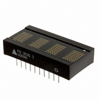
PD3535
Description
DISPLAY PROGR 4CHAR 5X7 HE RED
Manufacturer
OSRAM Opto Semiconductors Inc
Datasheet
1.PD3535.pdf
(14 pages)
Specifications of PD3535
Size / Dimension
1.40" L x 0.72" W x 0.29" H (35.56mm x 18.29mm x 7.24mm)
Color
Red
Number Of Digits
4
Character Size
0.27 in
Illumination Color
High Efficiency Red
Wavelength
630 nm
Maximum Operating Temperature
+ 85 C
Minimum Operating Temperature
- 40 C
Luminous Intensity
90 ucd
Viewing Area (w X H)
6.86 mm x 5.08 mm
Display Type
5 x 7 Dot Matrix
Lead Free Status / RoHS Status
Lead free / RoHS Compliant
Configuration
-
Voltage - Forward (vf) Typ
-
Millicandela Rating
-
Internal Connection
-
Lead Free Status / Rohs Status
Details
Other names
475-1421
PD3535
Q68000A7964
PD3535
Q68000A7964
Available stocks
Company
Part Number
Manufacturer
Quantity
Price
Company:

Part Number:
PD3535
Manufacturer:
STANLEY
Quantity:
9 200


DC Characteristics at 25°C
Parameter
V
I
I
PD243X
PD353X
PD443X
V
V
I
V
V
I
I
Data I/O Bus Loading
Clock I/O Bus Loading
Pin Assignments and Definitions
2006-01-23
CC
CC
IL
OH
OL
1)
Pin
1
2
3
4
5
6
7
8
9
10
CC
IL
IH
OL
OH
(except D0 to D7)
(Blank)
80 LEDs/unit (100% Bright)
D0 to D7 have no pull-up resistors so current is negligible.
Function
RD
CLK I/O
CLKSEL
RST
CE1
CE0
A2
A1
A0
GND
(1)
Definition
Active low, will enable a processor to read all
registers in the display.
If CLK SEL (pin 3) is low, then expect an exter-
nal clock source into this pin. If CLK SEL is
high, then this pin will be the master or source
into this pin. If CLK SEL is high, then this pin
will be the master or source for all other
devices which have CLK SEL low.
CLOCK SELECT determines the action of pin
2. CLK I/O, see the section on Cascading for
an example.
Reset. Used to synchronize blinking. Will not
clear the display. The reset pulse should be
less than 1 ms
Chip enable (active high).
Chip enable (active low).
Address input (MSB).
Address input.
Address input (LSB).
Ground.
Limits
Min.
4.5
—
—
—
2.0
25
—
2.4
–8.9
1.6
—
—
Typ.
5.0
2.5
115
145
150
—
—
—
—
—
—
—
—
—
7
Pin
11
12
13
14
15
16
17
18
19
20
Max.
5.5
3.5
130
165
170
0.8
—
100
0.4
—
—
—
100
240
Function
WR
D7
D6
D5
D4
D3
D2
D1
D0
V
CC
Units
Volts
mA
mA
mA
mA
Volts
Volts
µA
Volts
Volts
mA
mA
pF
pF
Definition
Write. Active low. If the device is selected, a
low on the write input loads the data into mem-
ory.
Data Bus bit 7 (MSB).
Data Bus bit 6.
Data Bus bit 5.
Data Bus bit 4.
Data Bus bit 3.
Data Bus bit 2.
Data Bus bit 1.
Data Bus bit 0 (LSB).
Positive power pin.
PD243X, PD353X, PD443X
Conditions
Nominal
V
V
V
V
V
V
V
V
V
V
V
—
—
CC
CC
CC
CC
CC
CC
CC
CC
CC
CC
CC
=5.0 V, A2 = 1, all other inputs low.
=5.0 V
=5.0 V
=5.0 V
=4.5 V to 5.5 V
=4.5 V to 5.5 V
=4.5 V to 5.5 V, V
=4.5 V to 5.5 V
=4.5 V to 5.5 V
=4.5 V, V
=4.5 V, V
OH
OL
=0.4 V
=2.4 V
IN
=0.8 V
Related parts for PD3535
Image
Part Number
Description
Manufacturer
Datasheet
Request
R

Part Number:
Description:
INTELLIGENT DISP 4CHAR 5X7 HERED
Manufacturer:
OSRAM Opto Semiconductors Inc
Datasheet:

Part Number:
Description:
DISPLAY 8DIGIT CERAMIC GREEN
Manufacturer:
OSRAM Opto Semiconductors Inc
Datasheet:

Part Number:
Description:
EMITTER IR 950NM 5MM SMD RADIAL
Manufacturer:
OSRAM Opto Semiconductors Inc
Datasheet:

Part Number:
Description:
LED TOPLED GREEN 570NM 2-PLCC
Manufacturer:
OSRAM Opto Semiconductors Inc
Datasheet:

Part Number:
Description:
INTERRUPTER RELFECT W/FILTR SMD
Manufacturer:
OSRAM Opto Semiconductors Inc
Datasheet:

Part Number:
Description:
LED Displays 5x7 Green 0.145 , 4-CHARACTER
Manufacturer:
OSRAM Opto Semiconductors Inc
Datasheet:

Part Number:
Description:
Q65110A4321_SIDELED PURE GREEN EOL150407
Manufacturer:
OSRAM Opto Semiconductors Inc
Datasheet:
Part Number:
Description:
Q65110A1202_RO DETECTOR 3/5MM_TR_RO
Manufacturer:
OSRAM Opto Semiconductors Inc
Datasheet:

Part Number:
Description:
PHOTODIODE 900NM 3MM W/FILTER
Manufacturer:
OSRAM Opto Semiconductors Inc
Datasheet:
Part Number:
Description:
INTELLIGENT DISP 4CHAR 5X7 HERED
Manufacturer:
OSRAM Opto Semiconductors Inc
Datasheet:
Part Number:
Description:
LED TOPLED GREEN 570NM 2-PLCC
Manufacturer:
OSRAM Opto Semiconductors Inc
Datasheet:
Part Number:
Description:
PHOTODIODE 900NM 3MM W/FILTER
Manufacturer:
OSRAM Opto Semiconductors Inc
Datasheet:

Part Number:
Description:
PHOTODIODE 850NM THRU-HOLE
Manufacturer:
OSRAM Opto Semiconductors Inc
Datasheet:

Part Number:
Description:
PHOTODIODE 880NM W/FILTER SMD
Manufacturer:
OSRAM Opto Semiconductors Inc
Datasheet: