CU40025-UW6J Noritake Company Inc, CU40025-UW6J Datasheet - Page 21
CU40025-UW6J
Manufacturer Part Number
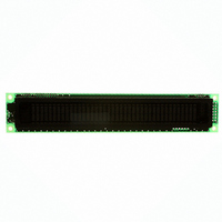
CU40025-UW6J
Description
MODULE VF DISPLAY 40X2 5MM CHAR
Manufacturer
Noritake Company Inc
Series
U-Versionr
Specifications of CU40025-UW6J
Outline L X W X H
182.00mm x 33.50mm x 20.50mm
Viewing Area
138.80mm L x 11.50mm W
Display Format
40 x 2
Display Type
Character
Format
5 x 7 Dots
Voltage - Supply
5V
Character Size
4.70mm H x 2.30mm W
Operating Temperature
-40°C ~ 85°C
Resolution
2 X 40
Viewing Area (h X W)
11.5mm X 138.8mm
Supply Current
300mA
Supply Voltage Range
4.75V To 5.25V
Character Format
Dot Matrix
Character Type
5x7 Dot Matrix
External Depth
21mm
External
RoHS Compliant
Product
Character Display Modules
Character Count X Line
40 x 2
Module Size (w X H X T)
182 mm x 33.5 mm x 20.5 mm
Voltage Rating
5 V
Operating Temperature Range
- 40 C to + 85 C
Current Rating
300 mA
Dot Format
5 x 7
Viewing Area (w X H)
138.8 mm x 11.5 mm
Interface
Parallel / Serial
Lead Free Status / RoHS Status
Lead free / RoHS Compliant
Number Of Dots
-
Lead Free Status / Rohs Status
Details
Other names
286-1062
Available stocks
Company
Part Number
Manufacturer
Quantity
Price
Company:

Part Number:
CU40025-UW6J
Manufacturer:
Noritake Company Inc
Quantity:
135


Notice for the Cautious Handling VFD Modules
Handling and Usage Precautions:
Please carefully follow the appropriate product application notes for proper usage, safety handling, and operation standards for
maximum performance.
[VFD tubes are made of glass]
[High voltage]
[Cable connection]
[Electrostatic charge]
[Structure]
[Power]
[Operating consideration]
[Storage and operating environment]
[Discard]
[Others]
Notice:
・We do not authorize the use of any patents that may be inherent in these specifications.
・Neither whole nor partial copying of these specifications are permitted without our approval.
・This product is not designed for military, aerospace, medical or other life-critical applications. If you choose to use this product
for these applications, please ask us for prior consultation or we cannot take responsibility for problems that may occur.
If necessary , please ask for assistance from our sales consultant.
•
•
•
•
•
•
•
•
•
•
•
•
•
•
•
•
•
•
•
•
•
•
•
Because the edges of the VFD glass-envelop are not smooth, it is necessary to handle carefully to avoid injuries to
your hands
Please avoid breaking the VFD glass-envelop to prevent injury from sharp glass particles.
The tip of the exhaust pipe is fragile so avoid shock from impact.
It is recommended to allow sufficient open space surrounding the exhaust pipe to avoid possible damage.
Please design the PCB for the VFD-module within 0.3 mm warping tolerance to avoid any forces that may damage the
display due to PCB distortion causing a breakdown of the electrical circuit leading to VFD failure.
Avoid touching conductive electrical parts, because the VFD-module uses high voltage exceeding 30∼100 volts.
Do not unplug the power and/or data cables of VFD-modules during operating condition because unrecoverable
damage may result.
Sending input signals to the VFD-module during a power off condition sometimes causes I/O port damage.
It is recommended to use a 30 cm or shorter signal cable to prevent functional failures.
VFD-modules needs electrostatic free packaging and protection from electrostatic charges during handling and usage.
During operation, VFD and VFD-modules generate heat. Please consider sufficient heat radiation dissipation using
We prefer to use UL grade materials or components in conjunction with VFD-modules.
Wrap and twist motion causes stress and may break VFDs & VFD modules. Please adhere to allowances within
0.3mm at the point of attachment.
Apply regulated power to the VFD-module within specified voltages to protect from failures.
Because some VFD-modules may consume in rush current equal to twice the typical current at power-on timing,
VFD-module needs a specified voltage at the point of connection. Please use an adequate power cable to avoid a
decrease in voltage. We also recommend inserting a power fuse for extra protection.
Illuminating phosphor will decrease in brightness during extended operation. If a fixed pattern illuminates for an
extended period,( several hours), the phosphor efficiency will decrease compared to the non operating phosphor
causing a non uniform brightness among pixels. Please consider programming the display patterns to use all
phosphor segments evenly. Scrolling may be a consideration for a period of time to refresh the phosphor condition
and improve even illumination to the pixels.
We recommend using a signal cable 30cm or less to avoid some possible disturbances to the signal.
Please use VFD-modules under the recommended specified environmental conditions. Salty, sulfur and dusty
Some VFDs contain a small amount of cadmium in the phosphor and lead in the solder. When discarding VFDs or
Although the VFD-module is designed to be protected from electrical noise, please plan your circuitry to exclude as
much noise as possible.
Do not reconstruct or repair the VFD-module without our authorization. We cannot assure the quality or reliability of
heat sink solutions.
we recommend using a sufficient power capability and quick starting of the power regulator.
unauthorized reconstructed VFD-modules.
Even when electric power is turned off, it may take more than one minute for the electrical current to discharge.
environments may damage the VFD-module even during storage.
VFD-modules, please adhere to governmental related laws or regulations.
20
CU40025-UW6J
Related parts for CU40025-UW6J
Image
Part Number
Description
Manufacturer
Datasheet
Request
R


Part Number:
Description:
MODULE VF GRAPHIC DISPLAY 112X16
Manufacturer:
Noritake Company Inc
Datasheet:

Part Number:
Description:
MODULE VF DISPLY 16X2 4.8MM CHAR
Manufacturer:
Noritake Company Inc
Datasheet:

Part Number:
Description:
MODULE VF GRAPHIC DISPLAY 140X16
Manufacturer:
Noritake Company Inc
Datasheet:

Part Number:
Description:
MODULE VF DISPLAY 20X2 EXT TEMP
Manufacturer:
Noritake Company Inc
Datasheet:

Part Number:
Description:
MODULE VF DISPLAY 24X2 5MM CHAR
Manufacturer:
Noritake Company Inc
Datasheet:

Part Number:
Description:
MODULE VF GRAPHIC DISPLAY 140X32
Manufacturer:
Noritake Company Inc
Datasheet:

Part Number:
Description:
MODULE VF DISPLAY 24X4 5V CHAR
Manufacturer:
Noritake Company Inc
Datasheet:

Part Number:
Description:
MODULE VF DISPLAY 20X2 5V CHAR
Manufacturer:
Noritake Company Inc
Datasheet:

Part Number:
Description:
MODULE VF DISPLAY 20X2 5V CHAR
Manufacturer:
Noritake Company Inc
Datasheet:

Part Number:
Description:
MODULE VF DISPLAY 24X4 5V CHAR
Manufacturer:
Noritake Company Inc
Datasheet:

Part Number:
Description:
MODULE VF DISP 16X2 8MM CHAR
Manufacturer:
Noritake Company Inc
Datasheet:

Part Number:
Description:
MODULE VF GRAPHIC DISPLAY 140X16
Manufacturer:
Noritake Company Inc
Datasheet:

Part Number:
Description:
MODULE VF DISPLAY 24X6 5V CHAR
Manufacturer:
Noritake Company Inc
Datasheet:

Part Number:
Description:
MODULE VF DISPLAY 24X6 5V CHAR
Manufacturer:
Noritake Company Inc
Datasheet: