CU40025-UW6J Noritake Company Inc, CU40025-UW6J Datasheet - Page 6
CU40025-UW6J
Manufacturer Part Number
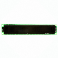
CU40025-UW6J
Description
MODULE VF DISPLAY 40X2 5MM CHAR
Manufacturer
Noritake Company Inc
Series
U-Versionr
Specifications of CU40025-UW6J
Outline L X W X H
182.00mm x 33.50mm x 20.50mm
Viewing Area
138.80mm L x 11.50mm W
Display Format
40 x 2
Display Type
Character
Format
5 x 7 Dots
Voltage - Supply
5V
Character Size
4.70mm H x 2.30mm W
Operating Temperature
-40°C ~ 85°C
Resolution
2 X 40
Viewing Area (h X W)
11.5mm X 138.8mm
Supply Current
300mA
Supply Voltage Range
4.75V To 5.25V
Character Format
Dot Matrix
Character Type
5x7 Dot Matrix
External Depth
21mm
External
RoHS Compliant
Product
Character Display Modules
Character Count X Line
40 x 2
Module Size (w X H X T)
182 mm x 33.5 mm x 20.5 mm
Voltage Rating
5 V
Operating Temperature Range
- 40 C to + 85 C
Current Rating
300 mA
Dot Format
5 x 7
Viewing Area (w X H)
138.8 mm x 11.5 mm
Interface
Parallel / Serial
Lead Free Status / RoHS Status
Lead free / RoHS Compliant
Number Of Dots
-
Lead Free Status / Rohs Status
Details
Other names
286-1062
Available stocks
Company
Part Number
Manufacturer
Quantity
Price
Company:

Part Number:
CU40025-UW6J
Manufacturer:
Noritake Company Inc
Quantity:
135


7.2. Display Clear
7.3. Cursor Home
7.4. Entry Mode Set
RS = 0
RS = 0
This instruction
1. Fills all location in the display data (DD) RAM with 20H (Blank character).
2. Clears the contents of the address counter to 0H.
3. Sets the display for zero character shift.
4. Sets the address counter to point to the DD RAM.
5. If the cursor is displayed, moves the cursor to the left most character in the top line
6. Sets the address counter to increment on each access of DD RAM or CG RAM.
This instruction
1. Clears the contents of the address counter to 0H.
2. Sets the address counter to point to the DD RAM.
3. Sets the display for zero character shift.
4. If the cursor is displayed, moves the left most character in the top line. (Line 1).
RS = 0
The I/D bit selects the way in which the contents of the address counter are modified after
every access to DD RAM or CG RAM.
The S bit enables display shift, instead of cursor shift, after each write or read to the DD RAM.
The direction in which the display is shifted is opposite in sense to that of the cursor. For
example if S=0 and I/D=1, the cursor would shift one character to the right after a CPU writes
to DD RAM. However if S=1 and I/D=1, the display would shift one character to the left and
the cursor would maintain its position on the panel.
DB7 DB6 DB5 DB4 DB3 DB2 DB1 DB0
DB7 DB6 DB5 DB4 DB3 DB2 DB1 DB0
DB7 DB6 DB5 DB4 DB3 DB2 DB1 DB0
(Line 1).
I/D = 1 : The address counter is incremented.
I/D = 0 : The address counter is decremented.
S = 1 : Display shift enabled.
S = 0 : Cursor shift enabled.
0
0
0
0
0
0
0
0
0
0
0
0
0
0
0
0
0
1
5
I/D
0
1
S
1
*
*: Don’t care
01H
02H to 03H
04H to 07H
CU40025-UW6J
Related parts for CU40025-UW6J
Image
Part Number
Description
Manufacturer
Datasheet
Request
R


Part Number:
Description:
MODULE VF GRAPHIC DISPLAY 112X16
Manufacturer:
Noritake Company Inc
Datasheet:

Part Number:
Description:
MODULE VF DISPLY 16X2 4.8MM CHAR
Manufacturer:
Noritake Company Inc
Datasheet:

Part Number:
Description:
MODULE VF GRAPHIC DISPLAY 140X16
Manufacturer:
Noritake Company Inc
Datasheet:

Part Number:
Description:
MODULE VF DISPLAY 20X2 EXT TEMP
Manufacturer:
Noritake Company Inc
Datasheet:

Part Number:
Description:
MODULE VF DISPLAY 24X2 5MM CHAR
Manufacturer:
Noritake Company Inc
Datasheet:

Part Number:
Description:
MODULE VF GRAPHIC DISPLAY 140X32
Manufacturer:
Noritake Company Inc
Datasheet:

Part Number:
Description:
MODULE VF DISPLAY 24X4 5V CHAR
Manufacturer:
Noritake Company Inc
Datasheet:

Part Number:
Description:
MODULE VF DISPLAY 20X2 5V CHAR
Manufacturer:
Noritake Company Inc
Datasheet:

Part Number:
Description:
MODULE VF DISPLAY 20X2 5V CHAR
Manufacturer:
Noritake Company Inc
Datasheet:

Part Number:
Description:
MODULE VF DISPLAY 24X4 5V CHAR
Manufacturer:
Noritake Company Inc
Datasheet:

Part Number:
Description:
MODULE VF DISP 16X2 8MM CHAR
Manufacturer:
Noritake Company Inc
Datasheet:

Part Number:
Description:
MODULE VF GRAPHIC DISPLAY 140X16
Manufacturer:
Noritake Company Inc
Datasheet:

Part Number:
Description:
MODULE VF DISPLAY 24X6 5V CHAR
Manufacturer:
Noritake Company Inc
Datasheet:

Part Number:
Description:
MODULE VF DISPLAY 24X6 5V CHAR
Manufacturer:
Noritake Company Inc
Datasheet: