HFBR-2115TZ Avago Technologies US Inc., HFBR-2115TZ Datasheet - Page 12
HFBR-2115TZ
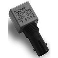
Manufacturer Part Number
HFBR-2115TZ
Description
RCVR MODULE 1300NM 125M 16DIP ST
Manufacturer
Avago Technologies US Inc.
Datasheet
1.HFBR-2115TZ.pdf
(12 pages)
Specifications of HFBR-2115TZ
Data Rate
125MBd
Voltage - Supply
4.5 V ~ 5.5 V
Power - Minimum Receivable
-34.5dBm
Current - Supply
82mA
Applications
General Purpose
Data Rate Max
0.1Gbps
Wavelength Typ
1300nm
Peak Reflow Compatible (260 C)
Yes
Leaded Process Compatible
Yes
Connector Type
Plastic ST
Lead Free Status / RoHS Status
Lead free / RoHS Compliant


22. All conditions of Note 21 apply except that
23. This value is measured during the
24. The Signal Detect output shall be
For product information and a complete list of distributors, please go to our website:
Avago, Avago Technologies, and the A logo are trademarks of Avago Technologies, Pte. in the United States and other countries.
Data subject to change. Copyright © 2006 Avago Technologies Pte. All rights reserved.
5965-3481E April 29, 2006
through their superposition (DCD and DDJ
are directly additive and RJ components
are rms additive). Specifically, when a
nearly ideal input optical test signal is
used and the maximum receiver peak-to-
peak jitter contributions of DCD (0.4 ns),
DDJ (1.0 ns), and RJ (2.14 ns) exist, the
minimum window time-width becomes
8.0 ns - 0.4 ns - 1.0 ns - 2.14 ns = 4.46 ns,
or conservatively 4.6 ns. This wider
window time-width of 4.6 ns guarantees
the FDDI PMD Annex E minimum window
time-width of 2.13 ns under worst-case
input jitter conditions to the Avago
receiver.
the measurement is made at the center of
the symbol with no window time-width.
transition from low to high levels of input
optical power.
asserted, logic-high (V
after a step increase of the Input Optical
Power. The step will be from a low Input
Optical Power, -45 dBm, into the range
between greater than P
The BER of the receiver output will be 10
or better during the time, LS_Max (15 s)
after Signal Detect has been asserted. See
Figure 12 for more information.
OH
A
, and -14 dBm.
), within 100 s
-2
25. This value is measured during the
26. Signal Detect output shall be deasserted,
transition from high to low levels of input
optical power. The maximum value will
occur when the input optical power is
either -45 dBm average or when the input
optical power yields a BER of 10
better, whichever power is higher.
logic-low (V
decrease in the Input Optical power from a
level which is the lower of -31 dBm or P
+ 4 dB (P
Signal Detect was de-asserted), to a
power level of -45 dBm or less. This step
decrease will have occurred in less than
8 ns. The receiver output will have a BER
of 10
until signal detect is de-asserted. The
input data stream is the Quiet Line State.
Also, Signal Detect will be de-asserted
within a maximum of 350 s after the BER
of the receiver output degrades above 10
for an input optical data stream that
decays with a negative ramp function
instead of a step function. See Figure 12
for more information.
-2
or better for a period of 12 s or
D
is the power level at which
OL
), within 350 s after a step
www.avagotech.com
-2
or
D
-2
Related parts for HFBR-2115TZ
Image
Part Number
Description
Manufacturer
Datasheet
Request
R

Part Number:
Description:
FIBER OPTIC CONN LATCH GRY SIMPL
Manufacturer:
Avago Technologies US Inc.
Datasheet:

Part Number:
Description:
FIBER OPTIC CONN LATCH BLU SIMPL
Manufacturer:
Avago Technologies US Inc.
Datasheet:

Part Number:
Description:
FIBER OPTIC CRIMPLESS CONN GRAY
Manufacturer:
Avago Technologies US Inc.
Datasheet:

Part Number:
Description:
FIBER OPTIC CONN BLUE SIMPLEX
Manufacturer:
Avago Technologies US Inc.
Datasheet:

Part Number:
Description:
FIBER OPTIC CONN LATCH DUPLEX
Manufacturer:
Avago Technologies US Inc.
Datasheet:

Part Number:
Description:
FIBER OPTIC CONN DUPLEX
Manufacturer:
Avago Technologies US Inc.
Datasheet:

Part Number:
Description:
FIBER OPTIC CONN GRAY SIMPLEX
Manufacturer:
Avago Technologies US Inc.
Datasheet:

Part Number:
Description:
FIBER OPTIC CBL DUPLEX 1=100M
Manufacturer:
Avago Technologies US Inc.
Datasheet:

Part Number:
Description:
FIBER OPTIC CBL DUPLEX 1=500M
Manufacturer:
Avago Technologies US Inc.
Datasheet:

Part Number:
Description:
FIBER OPTIC CBL CONN DUPLEX 5M
Manufacturer:
Avago Technologies US Inc.
Datasheet:

Part Number:
Description:
OPTOCOUPLER GATE DRV 2A 16-SOIC
Manufacturer:
Avago Technologies US Inc.
Datasheet:
Part Number:
Description:
OPTOCOUPLER 2CH 2.5A 16-SOIC
Manufacturer:
Avago Technologies US Inc.
Datasheet:

Part Number:
Description:
OPTOCOUPLER GATE DRV 0.4A 16SOIC
Manufacturer:
Avago Technologies US Inc.
Datasheet:

Part Number:
Description:
OPTOCOUPLER 2.0A 250KHZ 8-DIP
Manufacturer:
Avago Technologies US Inc.
Datasheet:

Part Number:
Description:
OPTOCOUPLER 2.0A 250KHZ GW 8-SMD
Manufacturer:
Avago Technologies US Inc.
Datasheet: