HFBR-57E0APZ Avago Technologies US Inc., HFBR-57E0APZ Datasheet - Page 2
HFBR-57E0APZ
Manufacturer Part Number
HFBR-57E0APZ
Description
TXRX MM SFP LC CONN BAIL DELATCH
Manufacturer
Avago Technologies US Inc.
Series
-r
Datasheet
1.HFBR-57E0ALZ.pdf
(16 pages)
Specifications of HFBR-57E0APZ
Applications
Ethernet
Mounting Type
SFP
Voltage - Supply
2.97 V ~ 3.63 V
Connector Type
LC Duplex
Wavelength
1300nm
Data Rate
155MBd
Supply Voltage
3.3V
Wavelength Typ
1300nm
Leaded Process Compatible
Yes
Lead Free Status / RoHS Status
Lead free / RoHS Compliant
Lead Free Status / RoHS Status
Lead free / RoHS Compliant, Lead free / RoHS Compliant
Available stocks
Company
Part Number
Manufacturer
Quantity
Price
Company:

Part Number:
HFBR-57E0APZ
Manufacturer:
Avago Technologies US Inc.
Quantity:
135


Loss of Signal
The Loss of Signal (LOS) output indicates that the optical
input signal to the receiver does not meet the minimum
detectablelevel for FDDI and OC-3 compliant signals.
When LOS is high it indicates loss of signal. When LOS is
low it indicates normal operation. The LOS thresholds are
set to indicate a definite optical fault has occurred (e.g.,
disconnected or broken fiber connection to receiver, failed
transmitter).
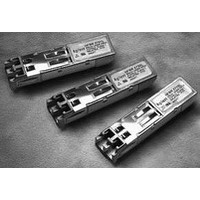
Module Package
The transceiver meets the Small Form Pluggable (SFP)
industry standard package utilizing an integral LC duplex
optical interface connector. The hot-pluggable capability
of the SFP package allows the module to be installed at
any time – even with the host system operating and on-
line. This allows for system configuration changes or
maintenance without system down time. The HFBR-57E0
uses a reliable 1300 nm LED source and requires a 3.3 V
dc power supply for optimal design.
Module Diagrams
Figure 1 illustrates the major functional components of
the HFBR-57E0. The connection diagram of the module is
shown in Figure 2. Figures 5 and 7 depict the external
configuration and dimensions of the module.
Installation
The HFBR-57E0 can be installed in or removed from any
MultiSource Agreement (MSA) – compliant Small Form
Pluggable port regardless of whether the host equipment
Figure 1. Transceiver functional diagram
2
OPTICAL INTERFACE
Light from Fiber
Light to Fiber
RECEIVER
TRANSMITTER
Photodetector
LED
Amplification &
Quantizattion
** Connect to Internal Ground.
Figure 2. Connection diagram of module printed circuit board.
is operating or not. The module is simply inserted,
electrical interface first, under finger pressure. Controlled
hot-plugging is ensured by design and by 3-stage pin
sequencing at the electrical interface. The module housing
makes initial contact with the host board EMI shield
mitigating potential damage due to Electro-Static
Discharge (ESD). The 3-stage pin contact sequencing
involves (1) Ground, (2) Power, and then (3) Signal pins,
making contact with the host board surface mount
connector in that order. This printed circuit board card-
edge connector is depicted in Figure 2.
EEPROM
LED DRIVER
20
19
18
17
16
15
14
13
12
11
TOP OF BOARD
V
TD-
TD+
V
V
V
V
RD+
RD-
V
EE
EE
CC
CC
EE
EE
T
T
R
R
T
R
ELECTRICAL INTERFACE
RD+ (Receive Data)
RD- (Receive Data)
Loss of Signal
TD+ (Transmit Data)
TD- (Transmit Data)
TX Disable
MOD-DEF2
MOD-DEF1
MOD-DEF0
(AS VIEWED THROUGH TOP OF BOARD)
10
1
2
3
4
5
6
7
8
9
BOTTOM OF BOARD
V
NC**
Tx Disable
MOD-DEF(2)
MOD-DEF(1)
MOD-DEF(0)
NC
LOS
V
V
EE
EE
EE
T
R
R
Related parts for HFBR-57E0APZ
Image
Part Number
Description
Manufacturer
Datasheet
Request
R

Part Number:
Description:
XMITTER OPTICAL 2MBD SERCOS
Manufacturer:
Avago Technologies US Inc.
Datasheet:
Part Number:
Description:
Fiber Optic Transmitters, Receivers, Transceivers SERCOS TRANSMITTER
Manufacturer:
Avago Technologies US Inc.

Part Number:
Description:
FIBER OPTIC CBL SIMPLEX 1=100M
Manufacturer:
Avago Technologies US Inc.
Datasheet:

Part Number:
Description:
FIBER OPTIC CBL SIMPLEX 1=500M
Manufacturer:
Avago Technologies US Inc.
Datasheet:

Part Number:
Description:
FIBER OPTIC CONN LATCH GRY SIMPL
Manufacturer:
Avago Technologies US Inc.
Datasheet:

Part Number:
Description:
FIBER OPTIC CONN LATCH BLU SIMPL
Manufacturer:
Avago Technologies US Inc.
Datasheet:

Part Number:
Description:
HDWR V-LINK CONN CRIMPLESS BLACK
Manufacturer:
Avago Technologies US Inc.
Datasheet:

Part Number:
Description:
RECEIVER FIBER OPTIC 600NM 5MBD
Manufacturer:
Avago Technologies US Inc.
Datasheet:

Part Number:
Description:
RECEIVER FIBER OPTIC 600NM 10MBD
Manufacturer:
Avago Technologies US Inc.
Datasheet:

Part Number:
Description:
RECEIVER FIBER OPTIC 5MBD TTL ST
Manufacturer:
Avago Technologies US Inc.
Datasheet:

Part Number:
Description:
RECEIVER FIBER OPTIC 600NM 40KBD
Manufacturer:
Avago Technologies US Inc.
Datasheet:

Part Number:
Description:
RCVR MOD FIBER OPTIC SERCOS SMA
Manufacturer:
Avago Technologies US Inc.
Datasheet:
Part Number:
Description:
RCVR FIBER OPTIC INTERBUS-S
Manufacturer:
Avago Technologies US Inc.
Datasheet:

Part Number:
Description:
RCVR OPT HI PERF VERS LINK HORZ
Manufacturer:
Avago Technologies US Inc.
Datasheet:
Part Number:
Description:
RCVR OPT HI PERF VERS LINK HORZ
Manufacturer:
Avago Technologies US Inc.
Datasheet: