AFBR-5930Z Avago Technologies US Inc., AFBR-5930Z Datasheet - Page 8
AFBR-5930Z
Manufacturer Part Number
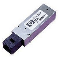
AFBR-5930Z
Description
TXRX SBCON 200MBD 2X5 DIP
Manufacturer
Avago Technologies US Inc.
Datasheet
1.AFBR-5930Z.pdf
(14 pages)
Specifications of AFBR-5930Z
Applications
General Purpose
Data Rate
200MBd
Wavelength
1300nm
Voltage - Supply
3.135 V ~ 3.465 V
Connector Type
MTRJ
Mounting Type
Through Hole
Data Rate Max
0.2Gbps
Supply Voltage
3.3V
Wavelength Typ
1300nm
Leaded Process Compatible
Yes
Lead Free Status / RoHS Status
Lead free / RoHS Compliant


Regulatory Compliance
These transceiver products are intended to enable com-
mercial system designers to develop equipment that com-
plies with the various international regulations governing
certification of Information Technology Equipment. See
the Regulatory Compliance Table for details. Additional
information is available from your Avago Technologies
sales representative.
Figure 6. Recommended Board Layout Hole Pattern
8
DIMENSIONS IN MILLIMETERS (INCHES)
NOTES:
1. THIS FIGURE DESCRIBES THE RECOMMENDED CIRCUIT BOARD LAYOUT FOR THE MT-RJ TRANSCEIVER PLACED
2. THE HATCHED AREAS ARE KEEP-OUT AREAS RESERVED FOR HOUSING STANDOFFS. NO METAL TRACES OR
3. 10 PIN MODULE REQUIRES ONLY 16 PCB HOLES, INCLUDING 4 PACKAGE GROUNDING TAB HOLES CONNECTED
4. THE SOLDER POSTS SHOULD BE SOLDERED TO CHASSIS GROUND FOR MECHANICAL INTEGRITY AND TO
AT .550 SPACING.
GROUND CONNECTION IN KEEP-OUT AREAS.
TO SIGNAL GROUND.
ENSURE FOOTPRINT COMPATIBILITY WITH OTHER SFF TRANSCEIVERS.
(0.425)
(0.525)
13.34
10.8
KEEP OUT AREA
FOR PORT PLUG
(0.299)
(0.276)
7.59
7
(0.118)
3
(1.063)
27
(0.055 ±0.004)
Ø 1.4 ±0.1
(0.236)
(0.118)
6
3
(0.28)
7.11
(0.18)
4.57
17.78
(0.7)
(0.055 ±0.004)
Ø 1.4 ±0.1
(0.07)
1.778
(0.121)
Electrostatic Discharge (ESD)
There are two design cases in which immunity to ESD
damage is important.
The first case is during handling of the transceiver prior to
mounting it on the circuit board. It is important to use nor-
mal ESD handling precautions for ESD sensitive devices.
These pre-cautions include using grounded wrist straps,
work benches, and floor mats in ESD controlled areas.
The second case to consider is static discharges to the ex-
terior of the equipment chassis containing the transceiver
parts. To the extent that the MT-RJ connector is exposed to
the outside of the equipment chassis it may be subject to
whatever ESD system level test criteria that the equipment
is intended to meet.
3.08
(0.28)
7.112
(0.121)
3.08
(0.14)
3.56
Ø 2.29
(0.09)
10.16
(0.4)
(0.378)
9.59
(0.032 ±0.004)
Ø 0.81 ±0.1
(0.55)
13.97
MIN.
Holes For
Housing
Leads
(0.079)
2
(0.055 ±0.004)
Ø 1.4 ±0.1
Related parts for AFBR-5930Z
Image
Part Number
Description
Manufacturer
Datasheet
Request
R

Part Number:
Description:
650nm FE Transceiver Eval Kit
Manufacturer:
Avago Technologies US Inc.
Datasheet:

Part Number:
Description:
TXRX OPT OC3 MTRJ SFF 2X5DIP
Manufacturer:
Avago Technologies US Inc.
Datasheet:

Part Number:
Description:
TXRX ETHERNET 125MBD MMF 2X5
Manufacturer:
Avago Technologies US Inc.
Datasheet:

Part Number:
Description:
TXRX OPT SFP DGTL 850NM IND
Manufacturer:
Avago Technologies US Inc.
Datasheet:

Part Number:
Description:
TXRX OPT SFF 4/2/1GBD 2X7
Manufacturer:
Avago Technologies US Inc.
Datasheet:

Part Number:
Description:
TXRX OPT SFP 4/2/1GBD 850NM
Manufacturer:
Avago Technologies US Inc.
Datasheet:

Part Number:
Description:
TXRX OPT XFP 10GB/S 850NM
Manufacturer:
Avago Technologies US Inc.
Datasheet:

Part Number:
Description:
TXRX OPT 1X9 100MBPS ST EXT TEMP
Manufacturer:
Avago Technologies US Inc.
Datasheet:

Part Number:
Description:
TXRX OPT 1X9 100MBPS SC EXT TEMP
Manufacturer:
Avago Technologies US Inc.
Datasheet:

Part Number:
Description:
TXRX OPT 1X9 100MBPS DUPLEX SC
Manufacturer:
Avago Technologies US Inc.
Datasheet:

Part Number:
Description:
OPTOCOUPLER GATE DRV 2A 16-SOIC
Manufacturer:
Avago Technologies US Inc.
Datasheet:
Part Number:
Description:
OPTOCOUPLER 2CH 2.5A 16-SOIC
Manufacturer:
Avago Technologies US Inc.
Datasheet:

Part Number:
Description:
OPTOCOUPLER GATE DRV 0.4A 16SOIC
Manufacturer:
Avago Technologies US Inc.
Datasheet:

Part Number:
Description:
OPTOCOUPLER 2.0A 250KHZ 8-DIP
Manufacturer:
Avago Technologies US Inc.
Datasheet:

Part Number:
Description:
OPTOCOUPLER 2.0A 250KHZ GW 8-SMD
Manufacturer:
Avago Technologies US Inc.
Datasheet: