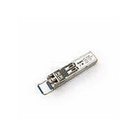
AFCT-5710PZ Avago Technologies US Inc., AFCT-5710PZ Datasheet - Page 2

AFCT-5710PZ
Manufacturer Part Number
AFCT-5710PZ
Description
TXRX OPT SFF PLUGGABLE BAIL
Manufacturer
Avago Technologies US Inc.
Series
-r
Datasheet
1.AFCT-5710LZ.pdf
(19 pages)
Specifications of AFCT-5710PZ
Data Rate
1.25Gbd
Wavelength
1310nm
Applications
Ethernet
Voltage - Supply
3.14 V ~ 3.47 V
Connector Type
LC Duplex
Mounting Type
SFP
Function
SFP Optical Transceivers with Optional DMI for Gigabit Ethernet 1.25 GBd. Intended for premise, public and access networking applications.
Product
Transceiver
Maximum Rise Time
0.26 ns/0.4 ns
Maximum Fall Time
0.26 ns/0.4 ns
Pulse Width Distortion
0.227 ns (Max)/0.267 ns (Max)
Operating Supply Voltage
3.14 V to 3.47 V
Maximum Operating Temperature
+ 85 C
Minimum Operating Temperature
- 10 C
Package / Case
SFP
Optical Fiber Type
TX/RX
Data Transfer Rate
1250MBd
Optical Rise Time
0.26/0.4ns
Optical Fall Time
0.26/0.4ns
Jitter
0.227/0.267ns
Operating Temperature Classification
Commercial
Peak Wavelength
1355nm
Package Type
SFP
Operating Supply Voltage (min)
3.14V
Operating Supply Voltage (typ)
3.3V
Operating Supply Voltage (max)
3.47V
Operating Temp Range
-10C to 85C
Mounting
Snap Fit To Panel
Pin Count
20
Lead Free Status / RoHS Status
Lead free / RoHS Compliant
For Use With
Singlemode Glass
Lead Free Status / RoHS Status
Lead free / RoHS Compliant, Lead free / RoHS Compliant
Available stocks
Company
Part Number
Manufacturer
Quantity
Price
Company:
Part Number:
AFCT-5710PZ
Manufacturer:
Avago Technologies
Quantity:
135
Overview
The AFCT-571 Z family is compliant with both IEEE
802.3Z (1000BASE-LX) and the SFP Multi-Source
Agreement (MSA) specification. These transceivers
are intended for premise, public and access network-
ing applications. They are qualified in accordance with
GR-468-CORE, and transmit data over single-mode
(SM) fiber for a link distance of 10 km, in excess of the
standard.
The AFCT-5715Z family of optical transceivers adds
digital diagnostic monitoring to standard SFP function-
ality, enabling fault isolation, components monitoring
and failure prediction capabilities.
General Features
The AFCT-571 Z is compliant to 1 GbE specifications.
This includes specifications for the signal coding, optical
fiber and connector types, optical and electrical trans-
mitter characteristics, optical and electrical receiver
characteristics, jitter characteristics, and compliance
testing methodology for the aforementioned.
This transceiver is capable of implementing both Single
Mode (SM) and Multimode (MM) optical fiber applica-
tions in that order of precedence in the event of con-
flicting specifications. In addition, the SM link type
exceeds the 2 m to 5 km 1000BASE-LX specification by
achieving compliance over 2 m to 10 km. The MM link
type is expected to meet the 62.5 μm MMF specification
when used with an “offset launch” fiber.
Figure 1. Transceiver Functional Diagram
2
Optical Interface
Light from Fiber
Light to Fiber
text
Receiver
Transmitter
Photo-Detector
Laser
Controller & Memory
Amplification
Quantization
SFP MSA Compliance
The product package is compliant with the SFP MSA
with the LC connector option. The SFP MSA includes
specifications for mechanical packaging and perfor-
mance as well as dc, ac and control signal timing and
performance.
The power supply is 3.3 V dc.
The High Speed I/O (HSIO) signal interface is a Low
Voltage Differential type. It is ac coupled and terminated
internally to the module. The internal termination is a
100 Ohm differential load.
Installation
The AFCT-571 Z can be installed in or removed from
any MSA-compliant Pluggable Small Form Factor (SFP)
port regardless of whether the host equipment is
operating or not. The module is simply inserted, elec-
trical-interface first, under finger-pressure. Controlled
hot-plugging is ensured by 3-stage pin sequencing
at the electrical interface. This printed circuit board
card-edge connector is depicted in Figure 2.
As the module is inserted, first contact is made by
the housing ground shield, discharging any poten-
tially component-damaging static electricity. Ground
pins engage next and are followed by Tx and Rx
power supplies. Finally, signal lines are connected. Pin
functions and sequencing are listed in Table 2.
&
Laser Driver &
Safety Circuit
Electrical Interface
MOD-DEF2 (SDA)
TD+ (Transmit Data)
MOD-DEF1 (SCL)
TD- (Transmit Data)
TX_FAULT
MOD-DEF0
TX_DISABLE
RD+ (Receive Data)
RD- (Receive Data)
Rx Loss Of Signal


