VSMF3710-GS08 Vishay, VSMF3710-GS08 Datasheet

EMITTER IR PLCC-2 HI SPD 890NM

VSMF3710-GS08

Manufacturer Part Number
VSMF3710-GS08
Description
EMITTER IR PLCC-2 HI SPD 890NM
Manufacturer
Vishay
Datasheets

Specifications of VSMF3710-GS08

Rise Time
30 ns
Radiant Intensity
10 mW/sr
Viewing Angle
120°
Current - Dc Forward (if)
100mA
Radiant Intensity (ie) Min @ If
6mW/sr @100mA
Wavelength
890nm
Voltage - Forward (vf) Typ
1.6V
Orientation
Top View
Mounting Type
Surface Mount
Package / Case
PLCC-2
Beam Angle
60 deg
Maximum Forward Current
100 mA
Maximum Power Dissipation
170 mW
Maximum Operating Temperature
+ 85 C
Minimum Operating Temperature
- 40 C
Fall Time
30 ns
Forward Current
100 mA
Forward Voltage
1.4 V
Lens Shape
Circular
Mounting Style
SMD/SMT
Peak Wavelength
890nm
Forward Current If(av)
100mA
Fall Time Tf
30ns
Supply Voltage Range
1.4V
Lead Free Status / RoHS Status
Lead free / RoHS Compliant
Lead Free Status / RoHS Status
Lead free / RoHS Compliant, Lead free / RoHS Compliant
Other names
751-1253-2

Available stocks

Company
Part Number
Manufacturer
Quantity
Price
Part Number:
VSMF3710-GS08
Quantity:
239
Company:
Part Number:
VSMF3710-GS08
Quantity:
70 000
High Speed Infrared Emitting Diode, 890 nm, GaAlAs Double Hetero
DESCRIPTION
VSMF3710 is an infrared, 890 nm emitting diode in GaAlAs
double hetero (DH) technology with high radiant power and
high speed, molded in a PLCC-2 package for surface
mounting (SMD).
Note
Test conditions see table “Basic Characteristics”
Note
MOQ: minimum order quantity
** Please see document “Vishay Material Category Policy”:
Document Number: 81241
Rev. 1.7, 03-Nov-09
PRODUCT SUMMARY
COMPONENT
VSMF3710
ORDERING INFORMATION
ORDERING CODE
VSMF3710-GS08
VSMF3710-GS18
I
e
For technical questions, contact:
(mW/sr)
10
94 8553
Tape and reel
Tape and reel
PACKAGING
www.vishay.com/doc?99902
ϕ (deg)
± 60
emittertechsupport@vishay.com
MOQ: 7500 pcs, 1500 pcs/reel
MOQ: 8000 pcs, 8000 pcs/reel
FEATURES
• Package type: surface mount
• Package form: PLCC-2
• Dimensions (L x W x H in mm): 3.5 x 2.8 x 1.75
• Peak wavelength: λ
• High reliability
• High radiant power
• High radiant intensity
• Angle of half intensity: ϕ = ± 60°
• Low forward voltage
• Suitable for high pulse current operation
• High modulation band width: f
• Good spectral matching with Si photodetectors
• Floor life: 168 h, MSL 3, acc. J-STD-020
• Lead (Pb)-free reflow soldering
• AEC-Q101 qualified
• Compliant to RoHS directive 2002/95/EC and in
• Find out more about Vishay’s Automotive Grade Product
APPLICATIONS
• High speed IR data transmission
• High power emitter for low space applications
• High performance transmissive or reflective sensors
accordance to WEEE 2002/96/EC
requirements at:
REMARKS
λ
www.vishay.com/applications
p
890
(nm)
p
Vishay Semiconductors
= 890 nm
c
= 12 MHz
PACKAGE FORM
VSMF3710
PLCC-2
PLCC-2
t
www.vishay.com
r
30
(ns)
1

Related parts for VSMF3710-GS08

VSMF3710-GS08 Summary of contents

Page 1

... I (mW/sr) e VSMF3710 10 Note Test conditions see table “Basic Characteristics” ORDERING INFORMATION ORDERING CODE VSMF3710-GS08 VSMF3710-GS18 Note MOQ: minimum order quantity ** Please see document “Vishay Material Category Policy”: Document Number: 81241 For technical questions, contact: Rev. 1.7, 03-Nov-09 FEATURES • Package type: surface mount • ...

Page 2

... VSMF3710 Vishay Semiconductors ABSOLUTE MAXIMUM RATINGS PARAMETER Reverse voltage Forward current Peak forward current Surge forward current Power dissipation Junction temperature Operating temperature range Storage temperature range Soldering temperature Thermal resistance junction/ambient Note °C, unless otherwise specified amb 180 160 140 ...

Page 3

... GaAlAs Double Hetero < 60 °C 0.05 100 20082 Fig Relative Radiant Power vs. Wavelength 8013 Fig Relative Radiant Intensity vs. Angular Displacement µs p 1000 emittertechsupport@vishay.com VSMF3710 Vishay Semiconductors 1.25 1.0 0.75 0.5 0.25 0 1000 800 900 λ - Wavelength (nm) 0° 10° 20° ...

Page 4

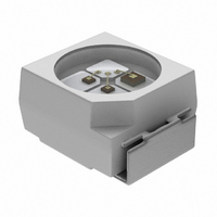
... VSMF3710 Vishay Semiconductors PACKAGE DIMENSIONS in millimeters 3.5 Pin identification C Ø 2.4 + 0.15 3 Drawing-No.: 6.541-5067.01-4 Issue: 5; 04.11.08 20541 SOLDER PROFILE 300 255 °C 250 240 °C 217 °C 200 max 150 max. 100 s max. 120 s 100 max. ramp up 3 °C/s max. ramp down 6 °C/s ...

Page 5

... In order to prevent components from popping out of the blisters, the cover tape must be pulled off at an angle of 180° with regard to the feed direction. 94 8158 min. 75 empty compartments Carrier trailer emittertechsupport@vishay.com VSMF3710 Vishay Semiconductors 10.0 9.0 120° 4.5 3.5 13.00 2 ...

Page 6

... Vishay disclaims any and all liability arising out of the use or application of any product described herein or of any information provided herein to the maximum extent permitted by law. The product specifications do not expand or otherwise modify Vishay’ ...

Page 7

... Vishay product could result in personal injury or death. Customers using or selling Vishay products not expressly indicated for use in such applications their own risk and agree to fully indemnify and hold Vishay and its distributors harmless from and against any and all claims, liabilities, expenses and damages arising or resulting in connection with such use or sale, including attorneys fees, even if such claim alleges that Vishay or its distributor was negligent regarding the design or manufacture of the part ...

Related keywords