HLMP-P505-G0011 Avago Technologies US Inc., HLMP-P505-G0011 Datasheet - Page 10
HLMP-P505-G0011
Manufacturer Part Number
HLMP-P505-G0011
Description
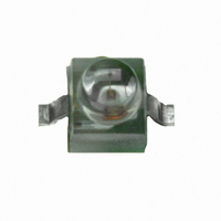
LED FLAT TOP GAP GRN CLEAR GW
Manufacturer
Avago Technologies US Inc.
Type
Uni-Colorr
Datasheet
1.HLMP-6505-L0021.pdf
(16 pages)
Specifications of HLMP-P505-G0011
Viewing Angle
125°
Mounting Type
Surface Mount
Color
Green
Millicandela Rating
6.3mcd
Current - Test
10mA
Wavelength - Dominant
569nm
Wavelength - Peak
565nm
Voltage - Forward (vf) Typ
2.1V
Lens Type
Clear
Lens Style/size
Round, 1.78mm
Package / Case
2-SMD, Gull Wing
Size / Dimension
2.09mm L x 2.21mm W
Height
2.44mm
Resistance Tolerance
569nm
Illumination Color
Green
Wavelength
569 nm
Luminous Intensity
6.3 mcd
Package Type
Flat Top
Emitting Color
Yellow Green
Test Current (it)
10mA
Forward Current
30mA
Dominant Wave Length
569nm
Forward Voltage
2.7V
Product Length (mm)
2.21mm
Product Height (mm)
2.44mm
Product Depth (mm)
2.34mm
Mounting
Surface Mount
Peak Wavelength
565nm
Shape Type
Circular
Main Category
Chip LED
Number Of Elements
1
Pin Count
2
Operating Temperature Classification
Industrial
Operating Temp Range
-40C to 100C
Reverse Voltage
5V
Lens Dimensions
1.91X1.91X0.82mm
Lead Free Status / RoHS Status
Lead free / RoHS Compliant
Luminous Flux @ Current - Test
-
Lead Free Status / Rohs Status
Lead free / RoHS Compliant
Other names
516-1793-2
HLMP-P505-G0011
HLMP-P505-G0011
Available stocks
Company
Part Number
Manufacturer
Quantity
Price
Company:

Part Number:
HLMP-P505-G0011
Manufacturer:
AVAGO
Quantity:
40 000
Company:
Part Number:
HLMP-P505-G0011
Manufacturer:
AVAGO
Quantity:
50 000


High Performance Green
Device
HLMP-
P502-F00xx
P505-G00xx
6500-F00xx
6505-L00xx
7040-D00xx
6800-G00xx
6820-F00xx
All
6800
6820
All
P505
6505
All Diffused
All
Notes:
1. The luminous intensity for arrays is tested to assure a 2.1 to 1.0 matching between elements. The average luminous intensity for an array
2. q
3. Dominant wavelength, l
4. Radiant intensity, I
10
determines its light output category bin. Arrays are binned for luminous intensity to allow I
candelas and h
1
/
2
is the off-axis angle where the luminous intensity is half the on-axis value.
v
Parameter
Luminous Intensity
Forward Voltage
(Nonresistor Lamps)
Forward Current
(Resistor Lamps)
Reverse Breakdown Voltage
Included Angle Between
Half Intensity Points
Peak Wavelength
Dominant Wavelength
Spectral Line Half Width
Speed of Response
Capacitance
Thermal Resistance
Luminous Efficacy
is the luminous efficacy in lumens/watt.
e
, in watts/steradian, may be calculated from the equation I
d
, is derived from the CIE Chromaticity Diagram and represents the single wavelength that defines the color of the device.
[4]
[1]
[2]
[3]
Symbol
I
V
I
V
2q
l
l
Dl
t
C
Rq
h
v
F
s
F
R
PEAK
d
v
1
J-PIN
1/2
/
2
Min.
1.0
1.6
1.0
10.0
0.4
1.6
1.0
5.0
e
Typ.
3.0
6.3
7.0
40.0
0.6
5.0
2.0
2.1
9.6
3.5
50.0
125
28
90
565
569
28
500
18
170
595
= I
v
/h
v
, where I
Max.
2.7
13.0
5.0
v
matching between arrays.
v
is the luminous intensity in
Units
mcd
V
mA
V
Deg.
nm
nm
nm
ns
pF
lm/W
C/W
Test Conditions
I
I
V
I
V
I
V
Junction-to-Cathode Lead
F
F
F
R
F
F
F
= 10 mA
= 2 mA
= 10 mA
= 100 A
= 5.0 Volts
= 5.0 V
= 0; f = 1 MHz
Related parts for HLMP-P505-G0011
Image
Part Number
Description
Manufacturer
Datasheet
Request
R

Part Number:
Description:
LED FLAT TOP GAP GRN CLR 3.7MM
Manufacturer:
Avago Technologies US Inc.
Datasheet:
Part Number:
Description:
LED FLAT TOP GAP GRN YOKE
Manufacturer:
Avago Technologies US Inc.
Datasheet:
Part Number:
Description:
LED FLAT TOP GAP GRN Z-BEND
Manufacturer:
Avago Technologies US Inc.
Datasheet:

Part Number:
Description:
LED, 1.91MM, GREEN, 6.3MCD, 569NM
Manufacturer:
Avago Technologies US Inc.
Datasheet:
Part Number:
Description:
General Purpose Visible Dome-Style LED,Green,Clear,LED-8c
Manufacturer:
Avago Technologies US Inc.
Datasheet:

Part Number:
Description:
OPTOCOUPLER GATE DRV 2A 16-SOIC
Manufacturer:
Avago Technologies US Inc.
Datasheet:
Part Number:
Description:
OPTOCOUPLER 2CH 2.5A 16-SOIC
Manufacturer:
Avago Technologies US Inc.
Datasheet:

Part Number:
Description:
OPTOCOUPLER GATE DRV 0.4A 16SOIC
Manufacturer:
Avago Technologies US Inc.
Datasheet:

Part Number:
Description:
OPTOCOUPLER 2.0A 250KHZ 8-DIP
Manufacturer:
Avago Technologies US Inc.
Datasheet:

Part Number:
Description:
OPTOCOUPLER 2.0A 250KHZ GW 8-SMD
Manufacturer:
Avago Technologies US Inc.
Datasheet:

Part Number:
Description:
OPTOCOUPLER 2CH 15MBD 3.3V 8SOIC
Manufacturer:
Avago Technologies US Inc.
Datasheet:
Part Number:
Description:
OPTOCOUPLER DARL-OUT 8-DIP
Manufacturer:
Avago Technologies US Inc.
Datasheet:
Part Number:
Description:
OPTOCOUPLER IGBT DRIVE 0.4A 8DIP
Manufacturer:
Avago Technologies US Inc.
Datasheet:
Part Number:
Description:
OPTOCOUPLER DARL-OUT 8-DIP
Manufacturer:
Avago Technologies US Inc.
Datasheet:

Part Number:
Description:
OPTOCOUPLER 1CH 1MBS 8-SMD GW
Manufacturer:
Avago Technologies US Inc.
Datasheet: