HLMP-P505-G0011 Avago Technologies US Inc., HLMP-P505-G0011 Datasheet - Page 4
HLMP-P505-G0011
Manufacturer Part Number
HLMP-P505-G0011
Description
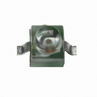
LED FLAT TOP GAP GRN CLEAR GW
Manufacturer
Avago Technologies US Inc.
Type
Uni-Colorr
Datasheet
1.HLMP-6505-L0021.pdf
(16 pages)
Specifications of HLMP-P505-G0011
Viewing Angle
125°
Mounting Type
Surface Mount
Color
Green
Millicandela Rating
6.3mcd
Current - Test
10mA
Wavelength - Dominant
569nm
Wavelength - Peak
565nm
Voltage - Forward (vf) Typ
2.1V
Lens Type
Clear
Lens Style/size
Round, 1.78mm
Package / Case
2-SMD, Gull Wing
Size / Dimension
2.09mm L x 2.21mm W
Height
2.44mm
Resistance Tolerance
569nm
Illumination Color
Green
Wavelength
569 nm
Luminous Intensity
6.3 mcd
Package Type
Flat Top
Emitting Color
Yellow Green
Test Current (it)
10mA
Forward Current
30mA
Dominant Wave Length
569nm
Forward Voltage
2.7V
Product Length (mm)
2.21mm
Product Height (mm)
2.44mm
Product Depth (mm)
2.34mm
Mounting
Surface Mount
Peak Wavelength
565nm
Shape Type
Circular
Main Category
Chip LED
Number Of Elements
1
Pin Count
2
Operating Temperature Classification
Industrial
Operating Temp Range
-40C to 100C
Reverse Voltage
5V
Lens Dimensions
1.91X1.91X0.82mm
Lead Free Status / RoHS Status
Lead free / RoHS Compliant
Luminous Flux @ Current - Test
-
Lead Free Status / Rohs Status
Lead free / RoHS Compliant
Other names
516-1793-2
HLMP-P505-G0011
HLMP-P505-G0011
Available stocks
Company
Part Number
Manufacturer
Quantity
Price
Company:

Part Number:
HLMP-P505-G0011
Manufacturer:
AVAGO
Quantity:
40 000
Company:
Part Number:
HLMP-P505-G0011
Manufacturer:
AVAGO
Quantity:
50 000


Absolute Maximum Ratings at T
Parameter
DC Forward Current
Peak Forward Current
DC Forward Voltage
(Resistor Lamps Only)
Reverse Voltage (I
Transient Forward Current
(10 s Pulse)
Operating Temperature Range:
Storage Temperature Range
For Thru Hole Devices
Wave Soldering Temperature
[1.6 mm (0.063 in.) from body]
For Surface Mount Devices:
Reflow Soldering Temperature
Notes:
1. See Figure 5 for current derating vs. ambient temperature. Derating is not applicable to resistor lamps.
2. Refer to Figure 6 showing Max. Tolerable Peak Current vs. Pulse Duration to establish pulsed operating conditions.
3. The transient peak current is the maximum non-recurring peak current the device can withstand without failure. Do not operate these lamps at this
high current.
Non-Resistor Lamps
Resistor Lamps
4
R
[1]
= 100 A)
[2]
[3]
Standard
Red
50
1000
5
2000
-55 to +100
A
= 25 C
DH AS
AlGaAs
Red
30
300
5
500
-40 to +100
High
Eff.
Red
30
90
6
5
500
260 C for 20 seconds
260 C for 5 seconds
-55 to +100
55 to +100
-40 to +85
Orange
30
90
5
500
Yellow
20
60
6
5
500
High Perf.
Green
30
90
6
5
500
-40 to +100
-20 to +85
Emerald
30
6
5
Green
90
500
-20 to +100
mA
mA
V
V
mA
Units
C
C
Related parts for HLMP-P505-G0011
Image
Part Number
Description
Manufacturer
Datasheet
Request
R

Part Number:
Description:
LED FLAT TOP GAP GRN CLR 3.7MM
Manufacturer:
Avago Technologies US Inc.
Datasheet:
Part Number:
Description:
LED FLAT TOP GAP GRN YOKE
Manufacturer:
Avago Technologies US Inc.
Datasheet:
Part Number:
Description:
LED FLAT TOP GAP GRN Z-BEND
Manufacturer:
Avago Technologies US Inc.
Datasheet:

Part Number:
Description:
LED, 1.91MM, GREEN, 6.3MCD, 569NM
Manufacturer:
Avago Technologies US Inc.
Datasheet:
Part Number:
Description:
General Purpose Visible Dome-Style LED,Green,Clear,LED-8c
Manufacturer:
Avago Technologies US Inc.
Datasheet:

Part Number:
Description:
OPTOCOUPLER GATE DRV 2A 16-SOIC
Manufacturer:
Avago Technologies US Inc.
Datasheet:
Part Number:
Description:
OPTOCOUPLER 2CH 2.5A 16-SOIC
Manufacturer:
Avago Technologies US Inc.
Datasheet:

Part Number:
Description:
OPTOCOUPLER GATE DRV 0.4A 16SOIC
Manufacturer:
Avago Technologies US Inc.
Datasheet:

Part Number:
Description:
OPTOCOUPLER 2.0A 250KHZ 8-DIP
Manufacturer:
Avago Technologies US Inc.
Datasheet:

Part Number:
Description:
OPTOCOUPLER 2.0A 250KHZ GW 8-SMD
Manufacturer:
Avago Technologies US Inc.
Datasheet:

Part Number:
Description:
OPTOCOUPLER 2CH 15MBD 3.3V 8SOIC
Manufacturer:
Avago Technologies US Inc.
Datasheet:
Part Number:
Description:
OPTOCOUPLER DARL-OUT 8-DIP
Manufacturer:
Avago Technologies US Inc.
Datasheet:
Part Number:
Description:
OPTOCOUPLER IGBT DRIVE 0.4A 8DIP
Manufacturer:
Avago Technologies US Inc.
Datasheet:
Part Number:
Description:
OPTOCOUPLER DARL-OUT 8-DIP
Manufacturer:
Avago Technologies US Inc.
Datasheet:

Part Number:
Description:
OPTOCOUPLER 1CH 1MBS 8-SMD GW
Manufacturer:
Avago Technologies US Inc.
Datasheet: