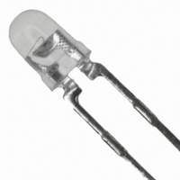
HLMA-KH00-J0000 Avago Technologies US Inc., HLMA-KH00-J0000 Datasheet - Page 4

HLMA-KH00-J0000
Manufacturer Part Number
HLMA-KH00-J0000
Description
LED 3MM ALINGAP HI PERF RED/ORN
Manufacturer
Avago Technologies US Inc.
Type
Uni-Colorr
Specifications of HLMA-KH00-J0000
Viewing Angle
45°
Package / Case
Radial - 2 Lead
Color
Orange-Red
Millicandela Rating
200mcd
Current - Test
20mA
Wavelength - Dominant
615nm
Wavelength - Peak
621nm
Voltage - Forward (vf) Typ
1.9V
Lens Type
Clear
Lens Style/size
Round, 3mm, T-1
Height
4.70mm
Mounting Type
Through Hole
Resistance Tolerance
615nm
Led Size
T-1
Illumination Color
Red-Orange
Lens Color/style
Untinted Non-Diffused
Operating Voltage
1.9 V
Wavelength
615 nm
Luminous Intensity
200 mcd
Mounting Style
Through Hole
Package Type
T-1
Emitting Color
Red Orange
Test Current (it)
20mA
Forward Current
50mA
Dominant Wave Length
615nm
Luminous Flux
0.5lm
Forward Voltage
2.4V
Product Length (mm)
3.43mm
Product Height (mm)
4.7mm
Product Depth (mm)
3.43mm
Mounting
Through Hole
Peak Wavelength
621nm
Shape Type
Circular
Chip Material
AlGaInP
Main Category
Standard LED
Number Of Elements
1
Pin Count
2
Operating Temperature Classification
Industrial
Operating Temp Range
-40C to 100C
Reverse Voltage
5V
Lens Dimensions
3.18x3.18x3.68mm
Lead Free Status / RoHS Status
Lead free / RoHS Compliant
Luminous Flux @ Current - Test
-
Lead Free Status / Rohs Status
Lead free / RoHS Compliant
Other names
516-1892
HLMA-KH00-J0000
HLMA-KH00-J0000
Available stocks
Company
Part Number
Manufacturer
Quantity
Price
Company:
Part Number:
HLMA-KH00-J0000
Manufacturer:
EVERLIGH
Quantity:
40 000
Company:
Part Number:
HLMA-KH00-J0000
Manufacturer:
AVAGO
Quantity:
50 000
Figure 3. Relative luminous intensity vs.
forward current. Derating based on T
Figure 6. Normalized luminous intensity vs. angular displacement.
For product information and a complete list of distributors, please go to our website:
Avago, Avago Technologies, and the A logo are trademarks of Avago Technologies Limited in the United States and other countries.
Data subject to change. Copyright © 2006 Avago Technologies Limited. All rights reserved. Obsoletes 5968-1439E
5989-3271EN June 30, 2006
1.0
0.9
0.8
0.7
0.6
0.5
0.4
0.3
0.2
0.1
0
100° 90° 80° 70° 60° 50° 40° 30° 20° 10° 0° 10° 20° 30° 40° 50° 60° 70° 80° 90° 100°
2.5
2.0
1.5
1.0
0.5
0.0
0
I
F
10
– DC FORWARD CURRENT – mA
20
– ANGULAR DISPLACEMENT – DEGREES
30
J
40
MAX.
50
Figure 4. Maximum forward current vs.
ambient temperature. Derating based on
T
J
Max = 110 C.
10
50
45
40
35
30
25
20
15
5
0
0
10 20
R
R
T
A
J-A
J-A
– AMBIENT TEMPERATURE – °C
= 618 °C/W
= 412 °C/W
30
40
50
www.avagotech.com
60
70 80
90
100
Figure 5. Maximum average current vs. peak
forward current.
50
40
20
30
10
0
50
I
PEAK
– PEAK FORWARD CURRENT – mA
f > 100 Hz
100
150
f > 1 KHz
f > 300 Hz
200


