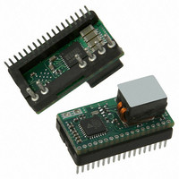
NDM1-12-120 CUI Inc, NDM1-12-120 Datasheet - Page 10

NDM1-12-120
Manufacturer Part Number
NDM1-12-120
Description
DIG CONV DC/DC POL 0.6~2.5V 12A
Manufacturer
CUI Inc
Series
Novum NDM1-12r
Type
Digital Point of Load (POL) Non-Isolatedr
Datasheet
1.NDM1-12-120.pdf
(19 pages)
Specifications of NDM1-12-120
Output
0.6 ~ 2.5V
Number Of Outputs
1
Power (watts)
30W
Mounting Type
Through Hole
Voltage - Input
8.5 ~ 14V
Package / Case
24-DIP Module
1st Output
0.6 ~ 2.5 VDC @ 12A
Size / Dimension
0.93" L x 0.50" W x 0.46" H (23.6mm x 12.7mm x 11.7mm)
Power (watts) - Rated
30W
Efficiency
95%
Lead Free Status / RoHS Status
Lead free / RoHS Compliant
Operating Temperature
-
3rd Output
-
2nd Output
-
Other names
102-2140
MODEL:
Figure 1: Recommended Circuit
OPERATING INFORMATION - POWER MANAGEMENT
INPUT FILTERING
The NDM1-12 module has built-in capacitances to
supply the pulsed current due to PWM switching.
However, to help minimize input voltage ripples,
additional input capacitance is recommended as
follows: 1x 330μF POSCAP or electrolytic and 3x 22μF
ceramic capacitors, placed as close as possible to the
input pins. (see Figure 1) If large, long-term load tran-
sients are present, additional bulk capacitances are
recommended, such as a 1000μF low-ESR electrolytic or
OSCON.
OUTPUT CAPACITANCE
The amount of output capacitance required depends on
the output ripple and noise requirements and transient
performance, even though the NDM1-12 POL
module does not require output capacitance for low
noise operations. As good starting point is 5x100μF
ceramic. (see Figure 1) These capacitors should be
placed as close to the load as possible. Additional high
frequency capacitors can be placed next to the load to
improve transient performance at the load.
AUTO-CONTROL™
The NDM1-12 utilizes an Auto-Control™ algorithm
to achieve stability and optimal transient response.
There is no need for any external compensation, as the
algorithm automatically takes into account the input
voltage, output voltage, load current conditions, and
output capacitance. Auto-control™ achieves this by
constantly monitoring the regulated output voltage on
a cycle-by-cycle basis and adjusting the parameters of
the controller to optimize the regulation. As the control
algorithm takes into account all variations in the power
stage, including operating conditions, component
variations and component aging, the control loop can
20050 SW 112
NDM1-12-120
th
Ave. Tualatin, Oregon 97062
a division of CUI INC
NDM1-12
DESCRIPTION:
phone 503.612.2300
maintain high gain up to as high a bandwidth as
stability will allow, resulting in highest loop
performance without sacrificing stability. The default
algorithm is configured for balanced ripple and noise
and transient response. The algorithm can be
customized for better ripple and noise or faster
transient response.
Auto-Control™ performance can be observed during
operation in the Demo tab of the V-Infinity Intelligence
Center GUI. As the regulation of a DC-DC converter
varies with load current, transient load step, amount of
bulk capacitance, inductor value etc.; so Auto-Control™
varies also to optimize the regulation.
The user has the ability to set the optimization goal of
the Auto-Control™ algorithm in the V-Infinity
Intelligence Center GUI. This is available on the GUI
Demo tab under “Optimization Factor”. Nine settings
are available, with 1 corresponding to the least
aggressive optimization, ideal for low ripple, and 9
corresponding to the most aggressive optimization,
ideal for fast transient response. The module defaults
to 5, and this is ideal for the majority of applications
where a good balance of noise and transient response
is desired.
Auto-Control™ also offers Quiet Mode and high ESR
Output Cap Optimization Mode options to achieve
different design goals.
Quiet Mode
When Quiet Mode is turned on the module is always
tuned to achieve the best regulation. Auto-Control™
will tune to a low value to give a low loop bandwidth,
minimizing the amplification of wide band noise
resulting in the lowest output deviation.
When Quiet Mode is turned off the module is always
tuned to achieve the best transient response. This
means that during load transients the module will tune
to a high Auto-Control™ value to give the highest loop
bandwidth and lowest sensitivity. When there is no
transient disturbance and the output voltage consists
mainly of wide bandwidth noise the module keeps
Auto-Control™ at a suitable value so that transient
bursts are well regulated. This may increase the ob-
served ripple during steady state load.
NON-ISOLATED DIGITAL DC-DC
POL CONVERTER
fax 503.612.2382 www.novumdigital.com
date
page
10/2010
10 of 19


